Flow Lines

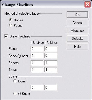
Use this feature to dynamically change the number of flowlines (U and V lines) used for wireframe representation of solids and surfaces. The parameters by which flowlines are to be edited are specified through the Change Flowlines dialog box that appears when Change Flowlines is selected from the Edit>Entities submenu.
Dialog Options:

Method of Selecting Faces
The radio buttons in the Method of Selecting Faces section can be used to specify whether bodies or faces will be used for selection for flowline modification. Regardless of the selection method, the entire body or sheet will be modified with the new settings.
Draw Flowlines
When selected, flowlines will be drawn and will appear in the model. Note that eliminating flowlines increases the speed of the operation and produces a less cluttered looking wireframe model. This checkbox is enabled by default.
U and V Lines
You can specify the number of U and V lines for planes, cylinders, spheres, torii and splines in the Flow Lines tab. Note that there are two available settings for Spline U and V lines: Equal and At Knots. The lower/upper range for each input field varies depending on the entity type:
Plane U lines, 0-16; V lines, 0-16
Cylinder U lines, 1-16; V lines, 0-16
Sphere U lines, 4-16; V lines, 1-16
Torus U lines, 1-16; V lines, 1-16
Splines U lines, 0-16; V lines, 0-16
The Change Flowlines option works similarly to the Draw Flowlines section of the Solids tab of the Tools>Options Set Configuration dialog box, except that the changes will be made only to existing bodies you select. (The Draw Flowlines options only affect the creation of new solid or sheet bodies.