Display
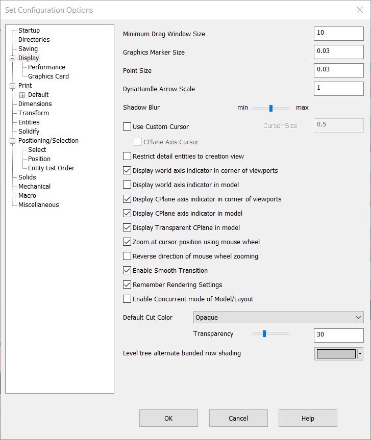
The settings available from the Display pane (Tools>Options>Display) allow you to control the various screen and interface display options, including cursor appearance, world and CPlane axis indicators, as well as overall screen size.
Dialog Options:
Minimum Drag Window Size
Depending on your working style, it may be desirable to increase or decrease this value, which controls how much you must move the cursor after clicking to create a selection window. If you find that you are defining windows when you only intend to single select, enter a higher number here (e.g., 20) to increase the movement necessary to define a window.
This also affects zoom by window. It increases the distance that the mouse must be moved before the program will zoom with a single click and drag instead of requiring two clicks. In both of these cases, the rubber band will start displaying once the minimum distance is reached.
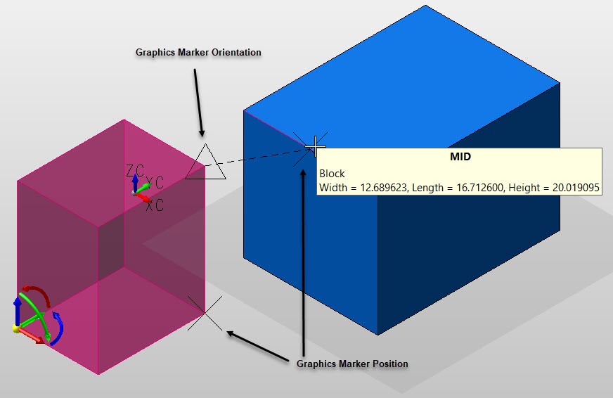
Graphics Marker Size
Sets the size by which the graphics marker will be displayed. The default value is 0.03. This means 3/100 th (3 percent) of the size of the viewport height. These markers are commonly used to indicate position and orientation durring position menu operations:
Point Size
Sets the size in which a point entity is displayed on the viewport. The default value is 0.03. This means 3/100 th (3 percent) of the size of the viewport height.
DynaHandle Arrow Size
Adjust the the overall size of DyanHandle in display.
Use Custom Cursor
You activate the Custom Cursor by checking it. The color attribute of this cursor can be set through the File>Properties>Settings dialog. The size of this cursor can be specified in this dialog page (see below) when this setting is enabled.
Cursor Size
You can specify a cursor size if and only if the Use Custom Cursor setting has first been enabled (see above).
CPlane Axis Cursor
Allows you to change the appearance of the cursor to represent the appearance of the CPlane axis indicator.
Restrict detail entities to creation view
By default, detail entities are visible in all views. When this setting is checked, detail entities will be visible only in the creation view.
Display world axis indicator in corner of viewports
When checked, the world axis indicator will appear in the lower left-hand corner of the viewport. The world axis indicator is displayed by default.
Display world axis indicator in model
When checked, the world axis indicator will be displayed within a model.
Display CPlane axis indicator in corner of viewports
When checked, the CPlane axis indicator will in appear in the upper right-hand corner of the viewport. The CPlane axis indicator is displayed by default.
Display CPlane axis indicator in model
When checked, the CPlane axis indicator will be displayed within the model at a fixed size. This setting is on (checked) by default.
Display Transparent CPlane in model
When checked, a transparent CPlane will be displayed at the CPlane depth when CP=DV.
Display Transparent Cutting Plane and Cutting Section in model
Select to display a cutting plane or cutting section in the viewport.
Zoom at Cursor Position Using the Mouse Wheel
When selected, mouse wheel zooming will be based on the cursor position in the window.
Reverse Direction of Mouse Wheel Zooming
When selected will modify the direction the zoom action makes in display (rolling mouse wheel.) Note that the amount of zoom can be controlled using the mouse driver properties (Windows>Control Panel>Mouse>Properties>Wheel.)
Remove Levels from Display Memory when Undisplayed
When enabled, information about undisplayed levels will not be held in memory. If you work with very large parts, you may find that enabling this option will result in better performance. The trade-off for this option is that it will take longer to toggle the display of levels that have previously been displayed during the current session.
Enable Smooth Transition
When enabled, view display changes such as changing view number, zoom, and pan, are performed as a series of incremental updates between the current view and the new view, instead of a single update. This can make it easier to understand how the new view relates to the old view, and provide a smooth "walk-through" of the part.
The incremental view change functions, which are tied to the arrow keys by default, do not use the smooth transition feature.
Remember Rendering Settings
Opening a part renders the viewports to be in the render mode they were in when the part was last saved.
Enable Concurrent Mode of Model/Layout
This option allows a model window and drawing layout window from the same part to be open simultaneously. When Concurrent Mode is enabled the title of each window will include the prefix "Model Window:" or "Layout Window:". If a drawing layout exists in a part, both a layout window and model window will be automatically opened when the part is edited/opened. If the active window is currently maximized only the active window will be seen (as would be expected). Using the tile or cascade functions in the Window menu will rearrange the windows so that both can be seen.
The title of the non-active window includes in parenthesis that the other mode, and thus the other window, is active. Setting the focus to either of the windows (by clicking on it) will not switch between model and layout mode. The Layout Toggle function is used to switch between layout and model modes as normal.
If Concurrent Mode is deactivated while a layout window and model window of the same part are open the non-active window will be automatically closed.
NOTE: The Concurrent Mode switch is also available as a function on the Edit>System Settings menu.
Default Cut Color
This setting allows for an Opaque or solids matched cut color for the View>Trim Plane functions.
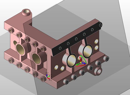
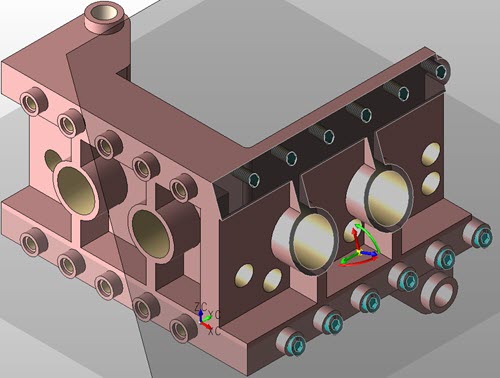
Transarency — Allows for a trim plane transarency gradient. A 0% setting will not show objects behind cut plane, while setting it to +0, (default is 10%) shows internal objects behind cut plane:
| 0% Transparency | 30% Transparency |
 |
 |
Level tree alternate banded row shading
This setiing allows for a change in color of level list alternate rows in Part Splitter Level Tree tab.