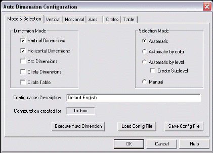
Mode & Selection
The Mode & Selection page of the Auto Dimension Configuration dialog contains settings specific to dimension and selection modes, and allows you to execute an auto dimension, load a previously saved configuration file, or save a new configuration file. These settings are explained below.
Dialog Options:

Dimension Mode
Select Dimension Modes from those available. Note that at least one Dimension Mode option must be checked in order for the OK, Execute Auto Dimension, and Save Config File settings to work. Note that a Dimension Mode setting must also be checked before the settings in its corresponding dialog page become active. For instance, the settings contained in the Vertical page would be grayed out if Vertical Dimensions is not first checked under Dimension Mode.
-
Vertical Dimensions – When checked, Auto Dimension will create Vertical Dimensions. Auto Dimension will dimension from the lowest selectable EndEnt to the second lowest selectable EndEnt, then from the second lowest to the third lowest, and so on, until all selectable EndEnts are dimensioned.
-
Horizontal Dimensions – When checked, Auto Dimension will create Horizontal Dimensions. Auto Dimension will dimension from the selectable EndEnt farthest on to the left, to the next selectable EndEnt, moving rightward. It will keep moving to the right, until all selectable EndEnts are dimensioned.
-
Arc Dimensions – When checked, Auto Dimension will create dimensions based on the Arcs dialog page configuration, which becomes active when Arc Dimensions is selected as a Dimension Mode.
-
Circle Dimensions – When checked, Auto Dimension will create dimensions based on the Circles dialog page configuration, which becomes active when Circle Dimensions is selected as a Dimension Mode.
-
Circle Table – When checked, Auto Dimension will create dimensions based on the Table dialog page configuration, which becomes active when Circle Table is selected as a Dimension Mode.
Selection Mode
The settings under Selection Mode allow you to specify how entities will be selected for dimensioning. The available options are explained below.
-
Automatic – When checked, all visible entities will be processed. The dimensions are created on the current level with the current system color attributes. If you are dimensioning in Layout Mode, each instance is separately processed. Note that only instances with standard views (1 to 6) in Layout Mode will be processed.
-
Automatic by Color – When checked, all the visible entities are processed by color. Each color attribute is processed separately. Dimensions are created on the current level with the color attributes of the entities that were processed. If you are dimensioning in Layout Mode, each instance is processed separately. Note that only instances with standard views (1 to 6) are processed.
-
Automatic by Level – When this setting is checked, all visible entities will be processed by level, and each level will be processed separately. When the Create Sublevel option is checked, Auto Dimension will create a sublevel on which the dimensions will be created using the level defaults of the processed level. If you are dimensioning in Layout Mode, each instance is processed separately. Note that only instances with standard views (1 to 6) are processed.
-
Manual – When checked, you will be prompted to select the entities to dimension using the Universal Selection Menu.
Configuration Description
This field displays a description of the current configuration. You are able to edit the description to include up to 35 characters.
Configuration Created For
Displayed in this field are the units in which the configuration was initially created. Note that if a configuration file is saved with a part file containing different units than those displayed, the configuration file will retain the units of the part file.
Execute Auto Dimension
Use this button to call the Automatic Dimension function. At the end, you will be returned to the Auto Dimension Configuration dialog, where you can make necessary changes and re-run the function.
Load Config File
Use this button to load a previously saved configuration file. The Open dialog will appear, with the files of type being (*.CDW).
Save Config File
This setting allows you to save the current configuration file to a .CDW extension, through the standard Save As dialog.