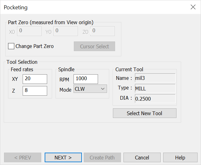
Pocketing Dialog
When you click Tools>Machinist>2D>Pocket, the Pocketing dialog appears shown below. Through this dialog you are able to specify Part Zero values and define the cutting tool.
NOTE: The machining view must be view 1 when using the 2D Pocket function. You can select all wireframe geometry as well as the edges of solids and sheet bodies to define the outer and inner boundaries.
Dialog Options:
Specify Part Zero values and define the cutting tool. When done, click the Next button to move on to the next dialog.

Part Zero (Measured from View Origin)
Specify X0, Y0 and Z0 values for Part Zero. This is the toolpath home position. This setting is unavailable by default. To change the current values, click the Change Part Zero setting. Click the Cursor Select button to define Part Zero with the cursor.
Tool Selection
Feed rates, spindle and other information relative to the current tool appear here. If no tool appears, click the Select a New Tool button. The Select the Active Tool dialog then appears, through which you can select a saved tool or define a new tool.
Click the Recommend button to access a feeds and speeds table based on part material and tool characteristics.