Using the 2D Drill Feature
This comprehensive drilling package allows you to create multiple toolpaths linked together in a collective. Each toolpath is associated with a different tool and canned cycle. A cycle database allows you to create and store your sequences of machine canned cycles with their different tools and sets of parameters.
Using this feature, you have the option of creating a separate toolpath for each tool and canned cycle. During post-processing, you have the option of selecting toolpaths either from the KeyCreator viewport, or from the toolpath table.
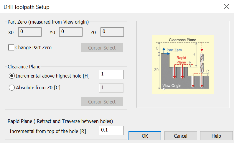
When this feature is selected, the Drill Toolpath Setup dialog appears, through which you are able to specify Part Zero, and Clearance and Rapid Plane settings, among others. Select OK to accept any changes made to the dialog. Additional dialogs then appear, as shown below.
Drill Toolpath Setup Dialog Options:

Part Zero (Measured from View Origin)
Specify Part Zero by checking the "Change Part Zero" setting, and specifying new X0, Y0, and Z0 values.
Clearance Plane
-
Incremental Above Highest Hole (H) – When checked, you are able to specify a new incremental value for clearance plane height.
-
Absolute from Z0 (C) – When checked, the clearance plane will be at the specified height absolute from the current Z0 setting.
Rapid Plane (Retract and Traverse Between Holes)
Specify a value for the Incremental from top of the hole (R) setting.
Drilling Cycle Definition (Fixed Cycles) Dialog
Drilling Cycle Definition (User Cycles) Dialog