Feature Setup
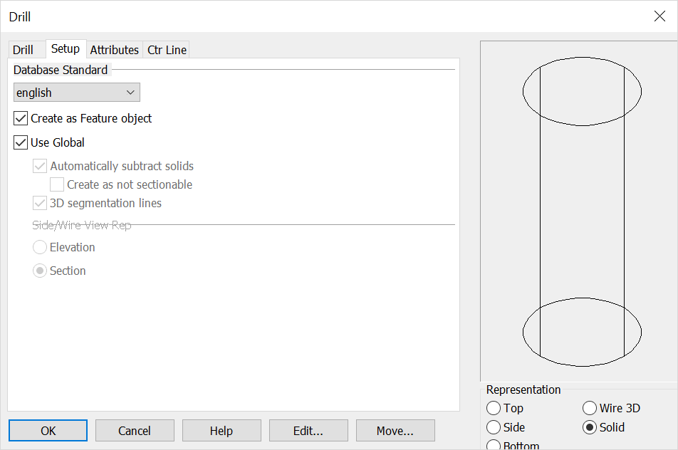
Each Feature dialog box contains a Setup tab that can be used to configure the feature.
Dialog Options:

Database Standard
Here you can specify database units (English/Metric).
Create as Feature Object
Specify whether the feature will be created as individual entities or as a single feature object. . If you choose to create a feature object, it includes data utilized by the Autolabel function.
Use Global
If this checkbox is enabled, the global settings for representation of solid and 2D/3D settings will be used. The global settings can be found in the "Set Configuration Options" dialog (Tools>Options>Mechanical tab).
Unchecked, you can configure the following options:
Automatically Subtract Solids
If checked, you will be prompted to select the solid body from which to subtract the feature hole(s). The geometry will then be removed from the solid to create the hole. Unchecked, the geometry representing the internal volume of the feature will be created as a solid object.
Create as not sectionable
Checked on will set the structural shape or mechanical element in a 'not to be sectioned' mode in any model mode or Layout Section operation. This mode can be set here or in the Edit\ Entities\ Set Not Sectionable and can be toggled on\off in Edit\ Generic Edit\ Rendering.
Side/Wire View Representation
If you have unchecked the Use Global checkbox, these options will be enabled. - You can choose to represent side views of the features (all views except Top and Bottom) as either an Elevation or a Section. The segmentation lines will be either dashed or solid, respectively. (Thread line display is also affected.)
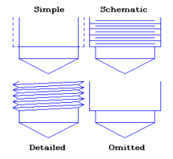
Thread Representation
-
Choose the type of thread representation desired for the feature. The options are Simplified, Schematic, Detailed, and Omitted. Note: This option is only available for certain types of features; those for which the standards include threads.
-
You can also choose to offset threads when defining your feature:
-
You may specify the number of coarse thread pitches to indicate the extra depth of the tapped hole. Click the # Threads radio button and enter values in the Normal and Bottom text fields. The accepted standard for the extra depth is four (4) thread pitches for normal tapped holes and one (1) thread pitch for bottom tapped holes.
-
You may, instead, specify a distance for the extra depth of normal and bottom tapped holes in either Inches (in) or Millimeters (mm). Click on the radio button for the units you want and enter a distance for the extra depth in the Normal and Bottom text fields.

Above > Available Thread Representations (section views shown)