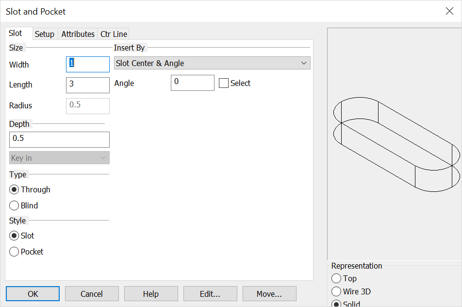
To create a Slot/Pocket feature, enter the information about the feature in the dialog box, which is shown below. Your selections will be reflected in the Preview window. A preview also shows during placement.
Dialog Options:

Width, Length, Radius
Select the Width, Length, and Radius for the slot or pocket.
Insert By
Choose an Insert By method.
The SLOT options are:
-
SLOT Center + Angle - Places the slot with the center of the feature on the point you select. The angle is set in the Angle section of the dialog box.
-
ARC Center + Angle - Places the slot with the center of the lower left arc of the feature on the point you select. The angle is set in the Angle section of the dialog box.
-
2 Arc Center Points - Places the slot with the centers of the left and right arcs on the points you select.
2 End Points - Places the slot by the two (X- Axis) endpoints of the slot.
The POCKET options are:
-
Pocket Center + Angle - Places the pocket with the center of the feature on the point you select. The angle is set in the Angle section of the dialog box.
-
Pocket Corner + Angle - Places the pocket with the lower left corner of the feature on the point you select. The angle is set in the Angle section of the dialog box.
-
2 Corner Points - Places the pocket with two diagonal corners on the points you select (at the current construction depth). The pocket sides are drawn along the X/Y axis.
Angle
Select an Angle for the slot/pocket. It is necessary to enter an angle here only when you are placing the slot/pocket using one of the Insert By options that include the angle in the insertion method (i.e., SLOT Center + Angle). If you click on the Select check box you will be asked to select another point to indicate the angle after you select the first point.
Depth
Choose a Depth for the slot/pocket. You can key in a depth in the input field or click on the pull down list for more options. The other choices are:
-
Line - Select an existing line. The line’s length will be used as the feature’s depth.
-
2 Pts - Choose two points to indicate the depth. The feature’s depth will be the distance between the two points.
-
Plane - Select a plane to indicate the feature depth. The depth will be the distance from the current construction plane to the selected plane. The selected plane must be parallel to the XY plane of the current Cplane.
Type
Select a representation Option for the slot/pocket (wire representations only). Choose either Blind or Through. If blind is selected the bottom lines of the slot are dashed. If through is selected, the bottom lines are drawn solid.
Style
Choose the feature you would like to create: Slot or Pocket.
Rep
Choose a Representation (view) for the pocket: Top, Wire 3D or Solid. Wire 3D and Solid representations are created in the -ZV direction.