Thickness

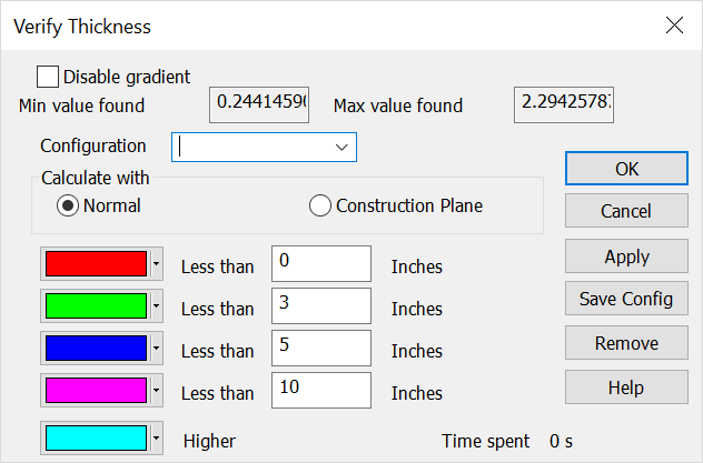
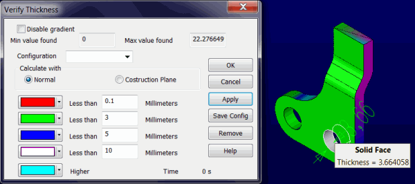
This function will determine the thickness of solid bodies. After choosing a solid to analyze moving the cursor over the solid will highlight features on the solid and a tool tip will provide the thickness for that feature. A color gradient can be set to visualize specific user defined thickness thresholds. In addition the solids overall maximum and minimum thickness is defined in the Verify Thickness Dialog.
Using this Function:
-
Set the View>Construction Plane if verifying thickness in a given plane not normal to the face of the features.
-
Open Tools>Verify>Distance>Thickness and use the Verify Thickness Dialog to set the behavior for the thickness analysis.
-
If using the color gradient the thickness thresholds will be viewed by color on the solid, when disabled no color gradient will exist, simply cursor move along the solid to verify thickness for a given feature in either the features face normal or the construction plane defined.
-
Thickness units are defined in File>Properties>Units/Tolerances.
Dialog Options:

Disable gradient
If you do not need to see the thickness gradient colors but still want to have the tool tip thickness show, check this on and the shading will be disabled.
Min/Max Value found
The thickness analysis computes both the highest and lowest thickness value for the given solid.
Configuration
Once the thickness threshold values and color scheme has been set you can use Save Config for use in later sessions.
Calculate with Normal/Construction Plane
Choose to either analyze along the features face normals or by the currently set Construction plane.
Thickness Threshold Color Settings
Pair each thickness threshold input with a desired color to project onto faces. The drop down color pallet gives you custom color options for each set. Use Apply to see changes made, once complete choose OK to see thickness gradient results. Remove will delete the custom configuration and cancel will abort the Verify Thickness session.
