Guidelines for Creating an Extrusion
Once you have specified how the extrusion is to be performed, and have OK’d these settings, you are then prompted to select the individual curves that comprise the closed planar profile to extrude.
It will be important to remember the following when selecting the planar profile:
-
All curves must be lines, arcs, conics, splines or polylines.
-
The order of selection is unimportant.
-
The entire set must represent a closed curve.
-
The entire set must lie on a plane
-
Multiple closed co-planar profiles may be chosen at once.
-
When choosing multiple profiles to extrude, it will be important to keep the following in mind:
-
Overlapping and intersecting profiles are automatically trimmed to one another.
-
Profiles that are intended to be holes within a larger outer profile are automatically detected and cut away.
Multiple Extrude Results:
There are several rules that will govern the resulting color of a solid when multiple profiles are used for extrude operations:
-
If the Get Attributes from Profile Geometry setting is enabled under Tools>Options>Solids, the attributes of the profile being extruded will be used for the result.
-
If the profiles are of different colors, the first one selected will determine the color of the resulting solid.
-
If the profiles are of different colors and ALLDISP>All or By Type is used to select the profile geometry type, the color of the first one encountered in the part file database will be used. This means that the database direction will also influence the color of the resulting solid.
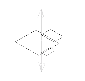
Below is an example of a simple extrusion using three closed rectangular profiles, selected using the ALLDISP>ALL method.

The direction vector for the extrusion appears once the profiles are selected.

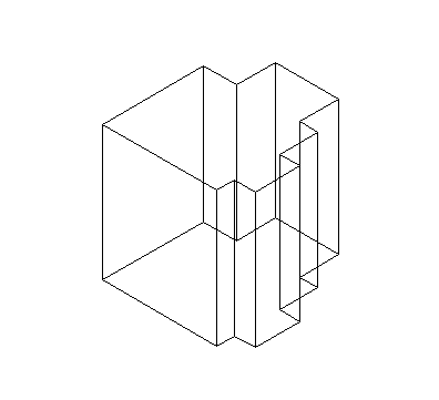
The result of an extrusion of the rectangular profiles by a value of 1 in the Z direction.

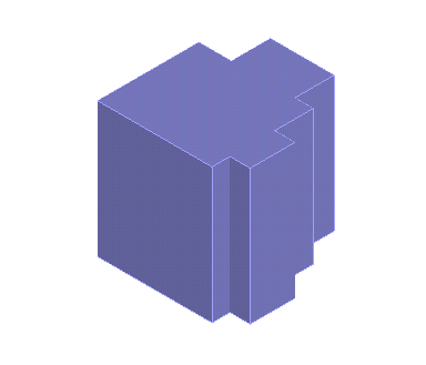
The extrusion result, displayed using the Smooth Shaded rendering option.