Sheetmetal Flange
This function allows you to create a flange. That is, it allows you to revolve a planar face of a solid about an axis that is derived from one of the face's edges. Then the face is extruded from a selected end by a specified distance.
Note: If the flange should not be bent from the whole area
of the selected face, you can use the Scribe function (Modify>Topology>Scribe) to section off a portion of the face before you create the flange.
Using the Function:
-
Select Create>Solid Feature>Sheetmetal Flange. The Create a Sheetmetal Flange dialog box appears. (See Dialog Options below.)
-
Specify the desired Bend Angle, Bend Radius and Bend Length, and click OK. (This example specifies 180, 0.5 and 100, respectively.) The prompt on the Conversation Bar instructs you to select the planar face you want to use to create the flange.
-
Select the desired face, as shown below.
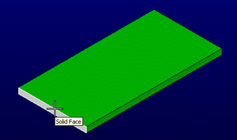
The prompt instructs you to select the edge that is the axis about which the flange revolves.
-
Select the desired edge, as shown below.
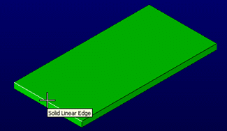
The flange is created, as shown below.
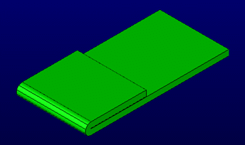
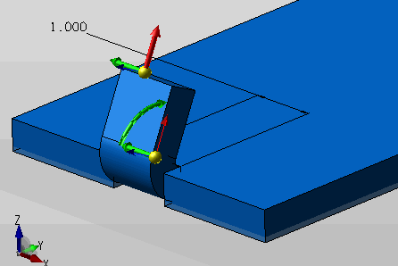
5. A set of dynahandles will allow adjustments of placement along the face as well as flange angle, length and width. Insure that the Flange Width is checked on to view dynahandle.
Create Flange Using DynaHandle
Dialog Options:
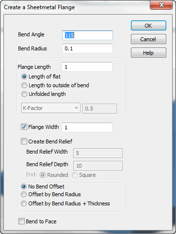
Bend Angle
The number of degrees to revolve the face
Bend Radius
How far from the face edge to place the axis used for the revolution
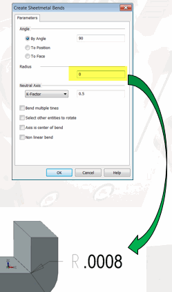
NOTE:Entering a value of 0 will create a 0.008 bend radius which is useful for any future sheet metal unbend actions.
Sheet Metal 0 Radius Bend
Flange Length
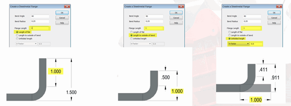
How far to extrude the revolved face. Choose the length option for the desired flange end result, (see below for examples) and any K-Factor.
Note: when the Include bend radius in length is unchecked this value plus the bend radius will be the final measure from the edge used to form the flange to the end of the flange, when checked the radius will be factored into the overall flange length ( an example where a bend radius of 10 and Flange Length 10, would result in just the bend being formed with no real flange produced.)
Flange Length Options
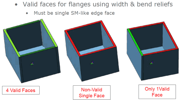
Flange Width
Independent setting of the flange width
Create Bend Relief
Creates a cut on each side of flange
Bend Relief Width
Set the width of the relief
Bend Relief Depth
How far into the sheet the relief will extend.
End
Choose the depth end condition as either round or square.
Offset Options
-
No Bend Offset: Does not move the bend
-
Offset by Bend Radius: Moves the bend backward a distance equal to the bend radius
-
Offset by Bend Radius+Thickness: Moves the bend a distance equal to the bend radius plus the sheetmetal's thickness
The three offset options allow the start of the bend to be offset backward. This allows for common sheetmetal operations where you want the sheetmetal part to maintain its dimensions (as opposed to building the part outward). The figure below illustrates each of these selections, respectively. The line in the figure corresponds to the face originally selected to create the flange.

Bend to Face
See the before and after examples below. This option allows you to select another face while creating the flange. The flange angle and offset are automatically set to cause the face of the flange to be close and parallel to the selected face. A slight gap is left between the two faces so that the modeler will not attempt to merge the two.
