Boss

Use this function to add material to a body, creating a boss. You select a solid body, and a closed planar chain of curves that form the extrusion profile. The profile might lie over the solid, on the face of a solid or within a cavity of the solid. You can select a solid or solid face in a part reference.
You specify forward and optional backward end conditions to define the extents of the extrusion, the draft angle if desired and choose the forward direction vector, and the protrusion is performed. Note that when the profile lies over the body you are adding material from the profile down to the body. When the profile lies on a face, you are adding material from the profile outward some distance.
Using the Function:
The required steps might change depending upon what settings are chosen in the dialog box for the function.
-
Select Boss from the Boss>Solid Feature submenu.
-
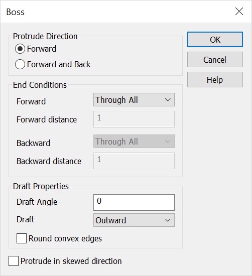
The Boss dialog box appears, from which you are able to specify a protrude direction, end conditions for the protrusion and draft properties. These settings are explained below. Once this dialog has been configured, select OK to accept the changes.
-
Select the solid to be modified.
-
Using the Universal Selection Menu, select the close planar profile(s).
-
Select the forward (or backward) face to protrude to.
-
Select the direction vector. The protrusion is then created per the specifications made through the Boss dialog box, and as you specified through the Conversation Bar menus.
Dialog Options:

Protrude Direction
The options under Protrude Direction allow you to specify either a Forward or Backward direction for the end condition.
-
Forward - When selected, the protrusion will be performed in a forward direction.
-
Forward and Back - When selected, the protrusion will be performed in both a forward and backward direction.
End Conditions
These options can be used to specify the distance and type of protrusion(s) in either a forward or backward direction, depending upon what you had selected under Protrude Direction. When you select one of the options requiring an extrusion distance, you may enter expressions in the distance boxes. The options available in the drop down boxes for the forward and backward end conditions are:
-
Through all - The profile is extruded up to the farthest face in the body onto which the profile projects.
-
Blind - The profile is extruded for a keyed in distance.
-
Offset from face - The profile is extruded up to the offset of a face that you select. You key in the offset value
-
Up to next face - The profile is extruded up to the closest face in the forward direction onto which the profile projects.
-
Up to face - The profile is extruded up to the selected face.
-
Up to a point - The profile is extruded for a distance equal to the distance from the point to the profile plane.
Draft Properties
The Draft Properties options allow you to specificy draft values.
-
Draft Angle - Enter an angle to be used when protruding with draft.
-
Draft - Select either Inward or Outward draft from the pull-down menu.
-
Round Convex Edges - When selected, the convex corners of the extruded profile will be rounded.
-
Protrude in Skewed Direction - Check the Protrude in skewed direction option when you want to specify the direction for the protrusion directly. When this box is not checked, the protrusion will be in the direction perpendicular to the planar profile curve. (When this option is checked, the drafting options are disabled.)
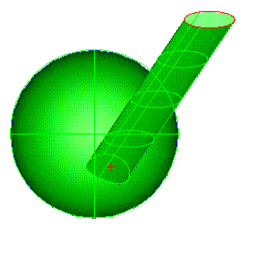
Below > This example used the center of the ellipse and a point on the sphere (created with the Extract Face Data function at a cursor pick point on the surface) to determine the protrusion vector. The protrusion direction was forward, and the end condition was up to next face. The Protrude in Skewed Direction box was checked. The ellipse was used as the closed planar curve profile. The vector was selected using the 2 points option with the points mentioned above.
