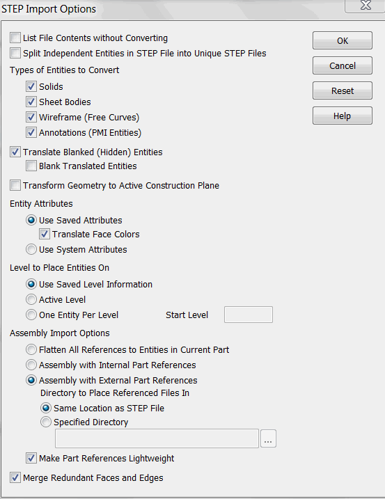
STEP Import Options Dialog
The following settings are available from the STEP Import Options dialog. Click the RESET button to restore all the settings in this dialog to their default configuration. When you have finished making your selections in the dialog box, click OK on the dialog.
Dialog Options:

List File Contents without Converting
Select to scan the file for basic information instead of having to wait until the translation completes to get these details. .
Split Independent Entities in Step Files into Unique Step Files
This will create individual files in a new folder in the Step file location.
Translate Blanked (Hidden) Entities
The import will be all inclusive. Check on the Blank Translated Entities to re-establish Blanking on imported blanked entities.
Transform Geometry to Active Construction Plane
This will place all geometry on the currently set construction plane.
Entity Attributes
-
Use Saved Attributes (default) - When selected, the RGB color attributes of the entities in the file are translated. When this setting is enabled, you can also elect to translate face colors.
-
Use System Attributes - When selected, the imported entities take on the current system attributes.
-
Translate Face Colors – When this setting is enabled, you can also elect to translate face colors.
Level Options
-
Place Entities using Saved Level Information (default) - When selected, layer information (if available) is translated. If the file was exported from KeyCreator, the level structure and level descriptor are preserved upon import.
-
Place Entities on Active Level - When selected, the imported entities are placed on the active level.
-
One Entity Per Level – When selected, levels will be dispersed so that no more than one (1) appears on a level. Specify the level number on which the first entity will be placed.
Assembly Import Options
-
Flatten All Components to Entities in Current Part – This option bursts the assembly being translated so that all part references are replaced by actual entities that get added to the active KeyCreator part
-
Assembly with Internal Part References – Creates a KeyCreator assembly in the current/active part of the open .ckd file. The assembly references other (new) parts in the same .ckd file.
-
Assembly with External Part References – Creates a KeyCreator assembly in the current/active part of the open .ckd file. The assembly references parts in other (new) .ckd files. The two options below allow you to choose the directory in which to place a converted .ckd file with external part references. These two options are unavailable when you select either Flatten All Components to Entities in Current Part or Assembly with External Part References.
-
Import files to directory of original file – Place the file in the directory where the original file resides
-
Import files to a selected directory – Place the file in the directory that you select, using the provided browse button. The default is the CKD directory path.
-
Make Part References Lightweight - When selected (Default), part references are made lightweight.
Merge Redundant Faces and Edges
Used to clean up geometry and reduce file size. On by default but if absolutely no changes are desired it should be unchecked.