Section View Dialog Options
Section View Dialog Options
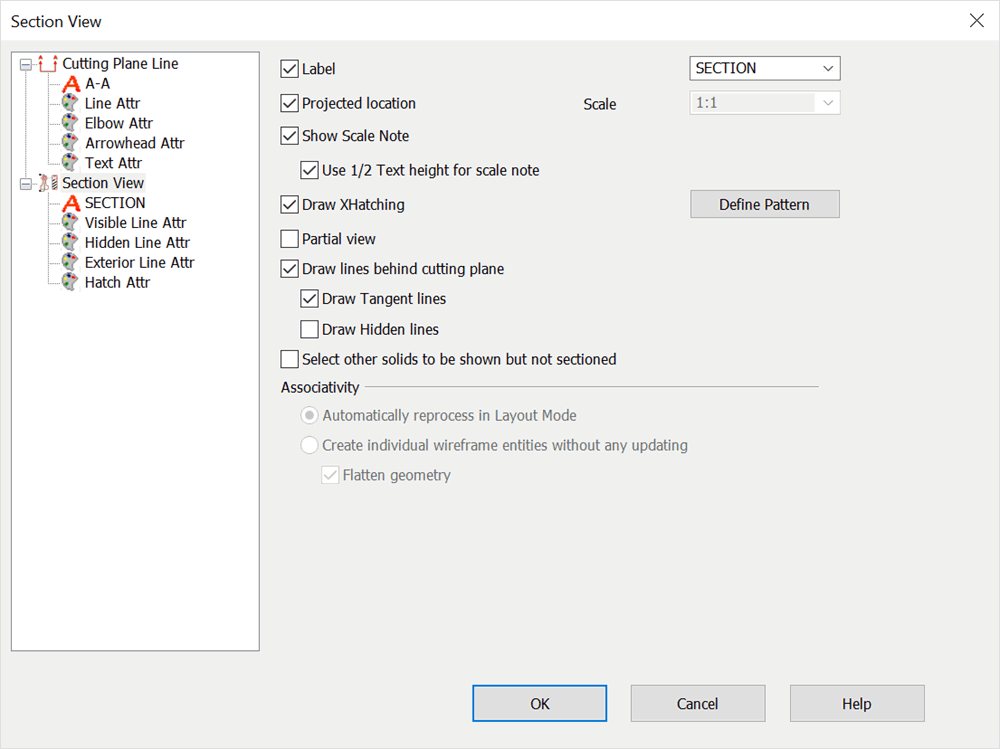
When you select Detail>Section View, and select the Section View tab, the pane appears as shown below. The dialog contains panes and content identical to the Cutting Plane Line dialog, with the addition of the Section View pane and attributes panes. The settings available on the Section View page are described below.
NOTE: The settings in the Detail>Section>Format tab are driven from the settings currently specified under the Detail>Settings>Settings> Format tab.
Dialog Options:

Label
Select a label for the section view from the pull-down menu.
Projected Location
Enable this checkbox to have the section view created directly parallel to the cutting line. Unchecked, you will be able to place the view anywhere on the screen. Also, if you are not creating projected views, you can specify a scale value for the view.
Scale
The Scale setting is enabled only if Projected Location is unchecked. This will scale the projection by the factor that you choose from the pull-down list. A scale identifier (for example, Scale 1:2) will be automatically included beneath the section view.
Show Scale Note
When selected, a note indicating the selected scale for the section appears under the selection label. The height of the scale note text is one-half the height of the selection label text when the Use 1/2 Text Height is checked on. For example, the user selects "1:1" in the Scale field and selects the Show Scale Note check box with 1/2 Text Height checked. As a result, the scale note "SCALE 1:1" is placed under the section label, for example, under "SECTION A-A." The height of the "SCALE 1:1" text is one-half the height of the "SECTION" text.
Spacing
Indicate a value for the distance between crosshatch lines.
Pattern
Select the crosshatch pattern that will show in the section view.
Partial View
A cutting plane line that determines a partial view doesn't completely cross the model, but instead stops within the model. This checkbox tells the section view whether to draw the broken lines or not.
Draw lines behind cutting plane
Checked on the section view will include any geometry that exists behind the dfined cutting plane line. Use the Draw Tangent and Draw Hidden lines check boxes to include either to the section view.
Select Other Solids to be Shown but not Sectioned
When creating the section view, you must select which solids will be cut. If you enable this checkbox, you can specify other solids to appear in the section view that aren’t cut.
In accordance with drafting standards, bolts and shafts are shown uncut.
Associativity
Use this section to indicate whether you want the section view to be associative, or if you wish to create a single representation of the section that won’t be automatically updated.
Flatten Geometry
When selected, extra lines that are not visible in the current view will be removed