Create Pipe Dialog Options
When Pipe is selected from the Create>Sweep menu, the Create Pipe dialog box is displayed. Through this dialog, you are able to specify a pipe standard (standard structural shapes) Outside diameter, Inside Diameter, wall thickness , and whether or not to Chain select pipe centerline curves.
Dialog Options:
Outside Diameter
The Outside Diameter will determine how large or small the diameter of the outside pipe wall will be.
Inside Diameter
The Inside Diameter is the diameter of the the inside pipe cavity. The value you specify for the Inside Diameter would effect this cavity.
Wall Thickness
An alternative to the I.D. would be to input a wall thickness (which would drive the I.D. value or vise versa.)
Chain Select Pipe Centerline Curves
The pipe centerline curves must exist prior to using this function. A single curve may be selected at the prompt, or a chain of curves may be selected if the Chain select checkbox is enabled. The chain of curves does not need to be coplanar, but if any curve is a spline, it must be a planar spline. Also, the chain of curves does not need to meet smoothly as sharp corners are handled automatically.
Setup:
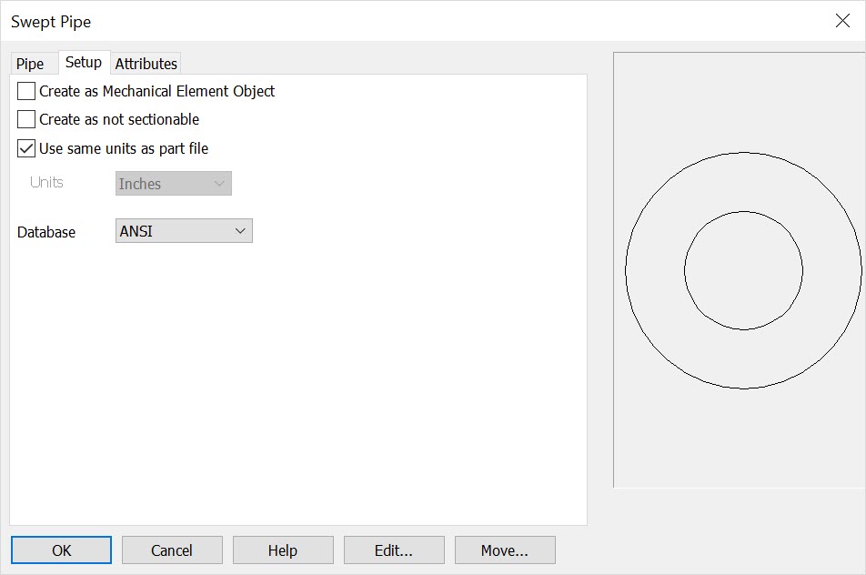
Create as Mech Elem Object
If enabled, shape entities will be grouped together to create a unique Mech Elem object. If left unchecked, shapes will be created as individual entities.
Create as not sectionable
Checked on will set the structural shape or mechanical element in a 'not to be sectioned' mode in any model mode or Layout Section operation. This mode can be set here or in the Edit\ Entities\ Set Not Sectionable and can be toggled on\off in Edit\ Generic Edit\ Rendering.
Use Same Units as Part File
Checked on the units of the object will follow that set for the part in File>Properties>Units/Tolerance. When unchecked you can define units from the drop down menu. Note that any detail work (such as creating a linear dimension) will follow the detail units set in Detail>Settings>Options>Primary units.
Units
Choose a unit standard from the pull-down list.
Database
Choose the ANSI, AISC or ANSI_M as available.
Attributes:

Width
This setting changes the line width. The available widths are 1, 3, 5, 7, 9, 11, 13, and 15 pixels.
Color
This setting changes the color . You can select any color from the palette. See Fille>Properties> Colors/Attributes for instructions for defining custom colors in your files.
Style
This setting changes the line type. Select a line style from the Styles box.
Flag
This setting changes the flag/pen numbers to graphic entities for plotting.
Level
Choose a level (or sub-level) for the entities to be created on. Levels you have named or otherwise defined will appear in this listbox as well.
Set from Entity
Click this button to select an entity in the drawing with the desired attributes that you want to use. The settings in the Attributes tab will then update to match the attributes of that entity.