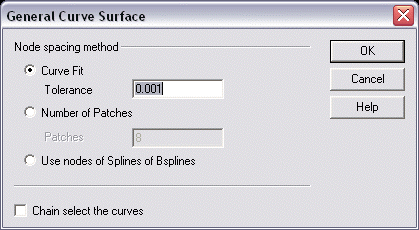
General Curve Surface Dialog Settings
The following settings are available from the General Curve Surface dialog box.
Dialog Options:

Node Spacing Method
Specify a node spacing method from the following options: Curve Fit, Number of Patches, and Use nodes of Splines and Bsplines.
-
Curve Fit - The Curve Fit option is tolerance based. The system will prompt for the curve fit tolerance. This is the maximum allowable deviation from the parent curves. While a curve fit surface is usually a better choice for automatic node placement because of its direct tolerance control, sometimes it can lead to an excessive number of patches required to conform to the parent curves within the specified toler ance. In this case, you can either increase the toler ance or switch to a given patch distrib ution.
-
Number of Patches - User defined. The system prompts for a number of patches across the surface. This directly relates to the number of points that will be taken from each curve. The Patches are the areas between the node points of the surface.
There is always one more point per curve than the number of patches to be bounded by that curve. For example: Two patches would mean three points per curve, three patches would mean four points per curve, and so on. If you are using Patches, be sure to specify a number of patches that will give the General Curve Surface feature enough data to accurately model each curve with the above-mentioned procedure. -
Use Nodes of Splines and Bsplines - Same node count on each spline. For this option, all input curves must be splines and all splines must have the same number of nodes. The placement of nodes has a direct and dramatic influence on the shape of a surface. Two surfaces, created from the same input curves but with different node distrib ution, will be two entirely different surfaces. Especially if the splines are closed, then the start and end points on each curve must be timed relative to the other curves.
Using existing nodes on splines provides the benefit of direct user-control over node placement, but you must place each node and ensure that each spline has the same number of nodes.
Additionally, because a surface must maintain proportionality between patch sizes, the arc length of each spline, and therefore the shape of the spline between each node, will be adjusted accordingly. Nonetheless, there are times when using existing nodes is imperative for maintaining surface shape.
The Use Nodes fitting method gives you exact control of the placement of nodes. This is useful in situations where node distribution is of higher priority than curve fit tolerance. Solids does extract tangent vectors from the splines at each node point to simulate the original curve as closely as possible, but ultimately, the arc length of each spline segment must be adjusted to maintain propor tionality to adjacent splines or overall surface smoothness will suffer.
Use Nodes has practical applications in everyday surface building chores. As illustrated above, building a very common geometric shape consisting of line-arc-line cross sections benefits substantially from the Use Nodes option. In this case, using the Curve Fit feature would produce a surface where the intended planar sections would not be planar at the ends, and the intended cylin drical section would be significantly distorted. -
Chain Select - Use the Chain Select option to allow chains of curves to be used as one curve.