Surfaces

A wireframe model can only define a surface at its edges. For surfaces like planar rectangles, this is sufficient. However, if a surface twists through 3D space, defining the edges is usually not sufficient. To have an exact model of a surface, you need to mathematically define the region between the edges. This allows you to perform exact intersections, projections and translations of a surface. Surfaces are defined at every point on the surface.
The surface creation functions will create bodies consisting of a single face. These faces can be combined into multi-face bodies using Stitch Two Bodies Together. Single face bodies can also be used to create intersections using the Generate Section Slice Between Two Solids feature. These faces can also be used like any other faces for the termination of a Sweep or Extrude operation.
Single surfaces or multiple surfaces combined together in bodies that do not form solids are often referred to as Surfaces.
Almost all free-form surfaces used in CAD are para metrically represented. The parameter space is defined by a two dim ensional coordinate system, the coordin ates of which are designated as 'U' and 'V', and have values that range between zero and one. Any point in this coordinate range defines a corresponding point in 3-D space exactly on the surface. This process is known as mapping from parameter to real space. The reverse of this is also true. Every point on a surface has a unique 'U, V' coordinate in parameter space.
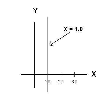
The U and V directions of a surface are just like the X and Y directions in a coordinate system. Recall from algebra that the graph of the curve X=1 is called an X curve and it runs parallel to the Y axis while going through the point at X=1.0 on the X axis. That is, an X curve (line) is perpendicular to the X axis and runs parallel to the Y axis. An X curve is called an X curve because it has a constant X value all along its path; whatever value Y has on the line, the X value is constant and equal to 1.0. The same is true for a constant U curve on a surface.

Above > The graph of the line x=1.0 is perpendicular to the x-axis.
To view information on a feature available from the Create>Surfaces submenu, click the appropriate link below:
Extrude Surface
Revolve Surface
Ruled
Edge Curves
Curve Mesh
Point-Vector
Planar
General Curve Interpolation
Constant Offset