Stretch

Use this function to stretch a part along an axis for a given distance, or to compress or squeeze a part together in a similar manner. The only region of the body the stretch affects is defined by the part of the body contained within two planes perpendicular to each end of the stretch axis. Solids, sheets and wireframe entities can be stretched and squeezed. You must indicate two points that define the stretch region. Perpendicular planes at each end of the line are intersected with the body and only that region between the planes is modified. If you think of the body as being clamped at these two planes then you can:
-
Fix one of the planes (by entering 0 for the distance at the position where you want the plane fixed)
-
Enter the same or different distance values for the 2 positions so that either
-
Both planes squeeze the body (both distances negative),
-
One squeezes and one stretches (one distance negative and the other positive), or
-
Both planes stretch the body (both distances positive)
Stretch creates law surfaces when the geometry of the stretch requires it, but it also maintains simple analytic geometry whenever possible. Law surfaces are one of the many spline surface types in ACIS. Law surfaces would be created anytime the stretch was done in such a way that the geometry was no longer a simple definition.
A law surface can be identified by using the Verify>Face function. Select the face to verify and a dialog box appears stating "This face type is: lawsur-spline." For example, if you stretch a cylinder using the centerline of the cylinder as the stretch axis, then the geometry of the cylinder does not really change. It just gets longer and the analytic cylinder is preserved with no need for a law surface. But if you use a stretch axis that runs at an angle to the centerline, then you create a different shape that most likely requires a law surface to be built.
Using the Function:
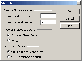
The required steps may change depending on how you configure the Stretch dialog.
-
Click Modify>Warp>Stretch. The Stretch dialog box appears, from which you are able to specify the distance to stretch, and the entity types to stretch.
-
Once you configure the dialog as desired, click OK.
-
Select the bodies to stretch.
-
Indicate the start point of the stretch region.
-
Indicate the end point of the stretch region. The stretch is performed.
Note that the stretch axis start and end points must lie within the body being stretched. To understand better this logic, think of a rubber band. If you stretch a rubber band using both of your hands, you have to hold the rubber band in both hands. You cannot hold it in the left hand only, while the right hand is beyond the bounds of the rubber band. Likewise, the endpoints of the stretch axis represent your left and right hands where they contact the rubber band.
Dialog Options:

-
From First Position – Enter the distance by which the body will be stretched with respect to the plane perpendicular to the stretch axis at the first position defining the axis. Note that positive values stretch the body and negative values squeeze the body.,/p>
-
From Second Position – Enter the distance by which the body will be stretched with respect to the plane perpendicular to the stretch axis at the second position defining the axis. Note that positive values stretch the body and negative values squeeze the body.
Type of Entities to Stretch
These options allow you to specify the entity types to stretch.
-
Solids or Surfaces - When selected, you will be able to stretch either solid or Surfaces.
-
Wires - When selected, you will be able to stretch Wireframe entities.

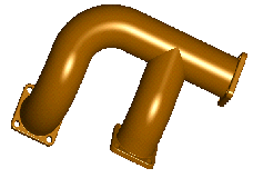
Above > A manifold part before stretching

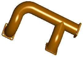
Above > A manifold after stretching 3 inches
Continuity Desired
-
G0 – Positional Continuity – This ensures positional continuity between the stretched and unstretched portions of the body.
-
G1 – Tangential Continuity – This ensures tangential continuity between the stretched and unstretched portions of the body.