Units/Tolerances
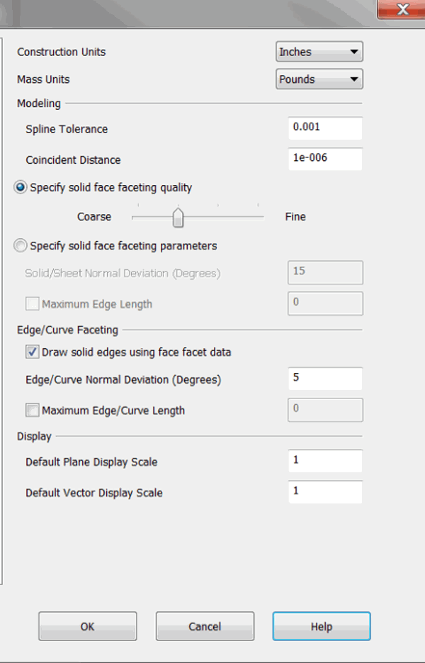
Through the Units and Tolerances dialog pane, you are able to configure constructions units and modeling and faceting settings.
Dialog Options:

Construction Units
This setting defines the construction units of the file. Choose inches, millimeters, feet, centimeters, yards, or meters from the drop-down menu. When the construction units of a part have changed, a prompt will appear to alert you.

When the construction units are changed, the following File Properties change:
-
Maximum Edge Length (if enabled)
-
Plane and Vector Display Scale
The Spline Tolerance value, in particular, is important to monitor. The number of nodes on a spline could be drastically affected by the changes to these values, depending on the size and curvature of the spline. A smaller tolerance caused a tighter fit of a bspline and, therefore, more node points are introduced into the bspline curve.
Changes to the Spline Tolerance value will affect the fit of bspline curves, and surfaces that ACIS constructs to match procedural curves and surfaces.
It is recommended that you do not change the spline tolerance and coincident distance values unless it is absolutely necessary. Tightening these tolerances may greatly increase file size, and significantly decrease performance. However, due to unusual design methods the flexibility to change these settings is provided.
These values change by an amount that is a soft conversion between the units. In other words, the values are not changed by a mathematical conversion. The conversion values are listed below, as converted from inches:
To Feet – 0.1
To Yards – 0.025
To Millimeters – 25
To Centimeters –"> To Meters – 0.025
If the construction units of a .PRT file when being converted to the .CKD format are in millimeters, the tolerances will be automatically set to the millimeter defaults.
Mass Units
Select from the drop-down the desired units for mass: pounds, ... , grams, ....
Modeling
Specify values for Spline Tolerance and Coincident Distance.
Solid Face/Faceting
Solid/Sheet Normal Deviation (degrees) - Degrees between two normals at the edge of a facet. Specifies accuracy with which facets represent the surface and the quality of desired rendering. This refinement control is independent of the model size. You can enter from 1 to 45 degrees.
For example, if the normal tolerance is 15 degrees (default), then all the adjacent nodes' normals have at most 15 degrees angle between them. Increasing this value causes fewer facets to be created. This results in coarser shading. Decreasing this value cause more facets to be created, which results in improved quality of rendering.
Note that if the following check box selected, an increase in the amount of facet data affects the display performance of the part and the size of the CKD file on disk: Save facets in design file to decrease load time at Tools>Options>Solids.
Maximum Edge Length – Length of the edge of a facet. This value allows the edge length to be within a specified limit. There is no other way to subdivide facets more in planar faces. A zero value in this field means that the maximum edge length is not considered in faceting.
Edge/Curve Faceting
Draw solid edges using face facet data – Checked on will use the same solid face parameters to facet the edge/curves on solids. This method improves display performance and matches the faceting for both for better visualixation. Unchecking this will show a reduction in performance (such as a slow down during redraws when rotating solids in display) and edge/curve to face display issues.
Edge/Curve Normal Deviation (degrees) – Allows you to define the tessellation for an arc, conic, spline and NURBS. It is the largest angle allowed between adjacent line segments in the tessellated representation.
Maximum Edge/Curve Length – Sets an upper limit on the length of a facet. A zero value in the field means that the maximum facet length is not considered when faceting.
Display
Specify a display scale for both Planes and Vectors.
Modeling Range
KeyCreator uses the ACIS modeling kernel for a range of modeling operations predominantly in the areas of solids and surface modeling.
In the ACIS modeling kernel, numbers in 3D space are represented as double precision floating point numbers that contain roughly 14-16 digits. Of these digits, 4 of the least significant digits are used for numerical round-off errors. Thus there are 10-12 digits available to represent small and large numbers. ACIS uses 10 digits to set tolerances used internally by its modeler
Given the limitation of having to use 10 digits to represent a number, the tradeoff is thus between the precision required (smallest number that you need to represent) and the range of numbers (determined by the largest number that you need to represent)
By default ACIS and thus KeyCreator uses a coincident distance of 1.0 e-06 (specified in File > Properties > Units/Tolerances). This value represents the smallest number that you need to represent. It also signifies the smallest feature you can model. Any two positions in the model that are separated by a distance less than this value are assumed to be coincident.
Representing a precision of 1.0 e-06 requires the use of 6 digits (.000001). Since ACIS uses 10 digits to represent numbers this effectively leaves us with 4 digits for the significant numbers. Thus the largest number that can be represented is 9999.999999
Any entity that is larger in dimension than ~10000 or any position that lies at a distance from the origin that is greater than ~10000 is considered to be ”r;outside the modeling range”
Examples of modeling ranges for typical design units:
Part Unit |
Smallest Number |
Largest Number |
|
Millimeter |
0.000001 MM (Or 1 nanometer) |
10000 MM (Or 10 meters) |
|
Inches |
0.000001 Inches (Or 1 micro inch) |
10000 Inches (Or 833 Feet or 278 yards) |