Feature Centerlines
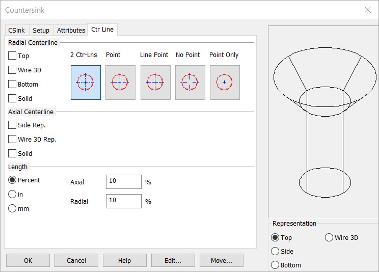
Each Feature dialog box contains a Ctr Line tab that can be used to add and configure centerlines the feature. Your selections will be reflected in the Preview window.
Dialog Options:

Radial Centerline
Use the checkboxes to indicate which views to include radial centerlines in (Top, Wire 3D, Bottom, Solid).
The push buttons can be used to specify the type of radial centerline to draw. The options are:
-
2-Ctr-Lins – Draws a horizontal and vertical centerline.
-
Point – Draws a point at the center of the hole.
-
Line Point – Draws centerlines and fixed lines representing the center point (as opposed to an actual point entity).
-
No Point – Draws lines but no center point.
-
Point Only – Draws only a center point.
Axial Centerline
Use the checkboxes to indicate which views to include axial centerlines in (Side Rep, Wire 3D Rep, Solid).
Length
Choose a length for the radial and axial centerlines. You can select whether to use a percentage or an inch or millimeter measurement to describe the length of the centerlines:
-
Percent – Using the percent method, you can specify a percentage of the radius or length of the hole that will correspond to the distance the centerline extends past the edge of the hole. For example, if the hole has a one inch radius and the radial percentage is set to 50%, then the radial centerline will extend ½ inch past the edge of the hole (i.e., 50%, or one-half the radius). The percent method for specifying the length of the centerline is useful if you have many features of varius sizes. The centerlines will always be proportional to the size of the hole.
-
Inch or mm – You can alternatively set a fixed length for the centerline. Choose either "in" for inches or "mm" for millimeters. The length you enter in the text fields will be the length the centerlines extend past the edge of hole. This length will stay fixed regardless of the size of the hole.