Angle Beam

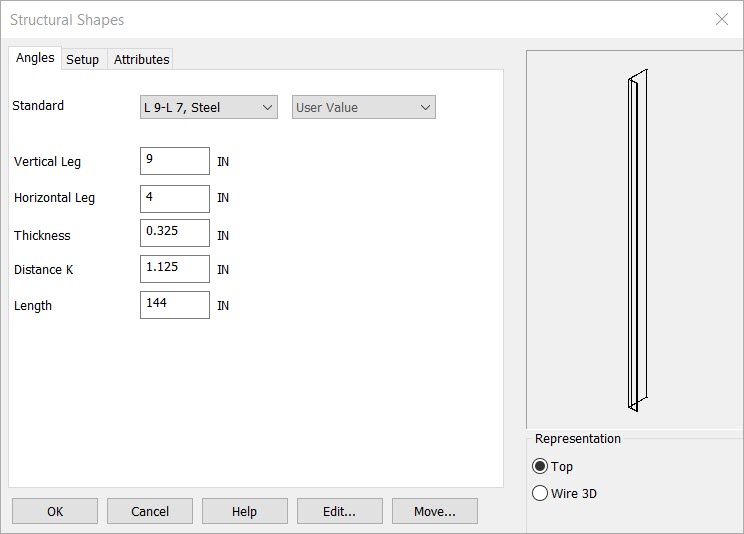
Select Angles to access the dialog box. The angle you are creating will be displayed in the Preview section of the dialog box.
Setup Dialog

Standard
Sets the Channel style and size or use the below options for custom setup.
Vertical Leg
The desired length of the vertical leg (units can be specified in the Setup tab of the dialog).
Horizontal Leg
This setting controls the desired length of the horizontal leg.
Thickness
This setting controls the overall thickness of the entire angle shape.
Distance K
To determine the exact "K" value for a given shape, you should consult the AISC "Manual of Steel Construction." A general rule of thumb is that the "K" value is roughly double the flange thickness (+/- 25%).
Length
Input a length for the Beam.
Rep
Choose a Representation for the shape:
-
Top - Creates a 2D top view of the shape. You will be prompted to digitize the shape bottom or center (depending on the type of shape).
-
Wire 3D - Creates a 3D wireframe view of the shape. You will be prompted to digitize the bottom or center of the shape (depending on the type). The shape will be generated in the -ZV direction in the current construction plane.
When complete choose OK or if you are editing an existing structural shape choose the Edit or move options
Using this Function
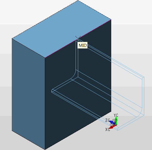
After choosing setup dialog options the conversation bar position menu allows placement of the structural shape by anchor point. The anchor point for the structural shape can be changed using the generic toggle and placement of the structural shape can be altered using the Toggle Current Selection. Below the channel is placed in the top- middle of the front face using both generic toogle and Toggle Current selection (Display view=7, Cplane=6.)
