Part Settings Interaction with Detail Style EditorKeyCreator / Detail / Overview / Part Settings Interaction with Detail Style EditorThis topic continues the discussion of How Detail Style Editor Affects Newly Created Detail Entities, which is part of the overall discussion of Using Detail Style Editor. Changes to the Part Settings toolbar can affect creating detail entities. This toolbar contains functions from the Edit>System Settings menu that control detail attributes. That is, the default Part Settings toolbar has the following functions (buttons), left-to-right: Line width, Ccolor, Line style. These same attributes, plus Pen, also are available as options on attributes panes of the Detail Style Editor dialog. The Part Settings toolbar shown below is a customized version to illustrate all four of the detail attributes.
For the purpose of explanation only, the table below uses levels to define how the attributes interact with each other. The lowest level, level 1, is when all attribute options are cleared on the Detail Options dialog. Level 2 (2A and 2B) represents those attributes that are common in the Detail Style Editor dialog. They override the level 1 attributes. Level 3 (3A and 3B) represents those that are local attribute options on the dialog. These are set for specific detail entities and override the common (level 2) options.
Examples of how these work are provided below using linear dimensions. The same concepts apply to all of the detail entities.
Creating a Dimension with Default SettingsThe Detail attributes pane, which is at the same level of the tree as the Detail lines and Formatting panes, controls the detail entity's entity attributes. The attributes you select on this pane are used when selecting entities with an attributes mask. Also, these are the attributes that the components of a detail entity use if not explicitly set on the component attribute panes of the Detail Style Editor dialog. By default, all the attributes on this pane are set to use the part settings (cleared). When you clear an attribute's check box on an attributes pane, the attribute is taken from the Part Setting toolbar when you create the detail entity. This is the same way that creating geometry uses the part settings.
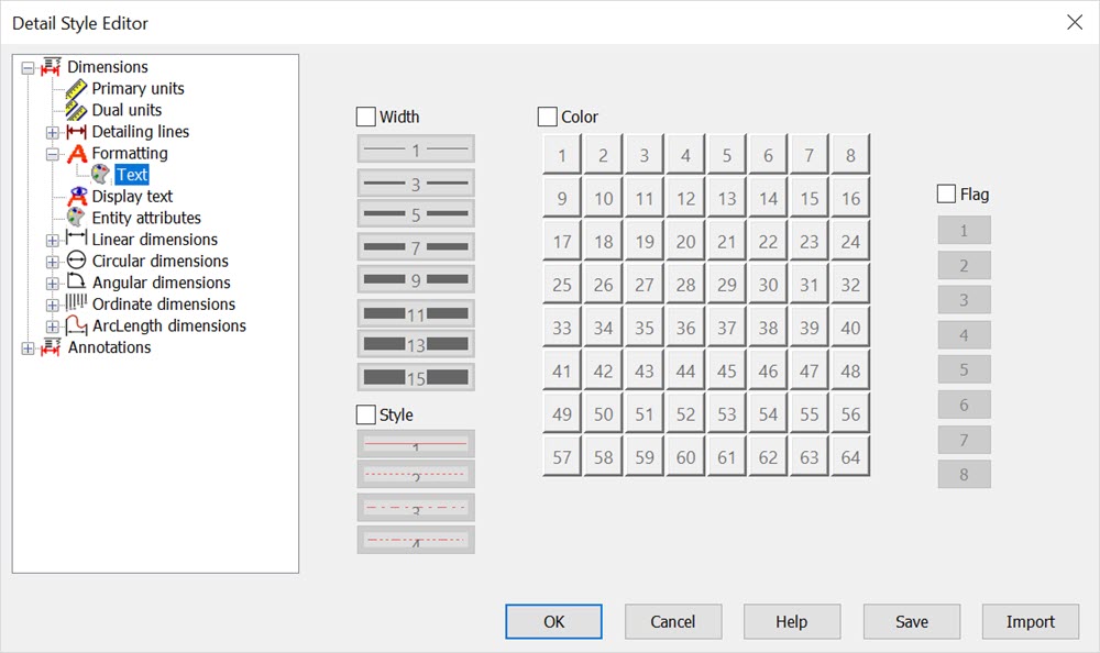
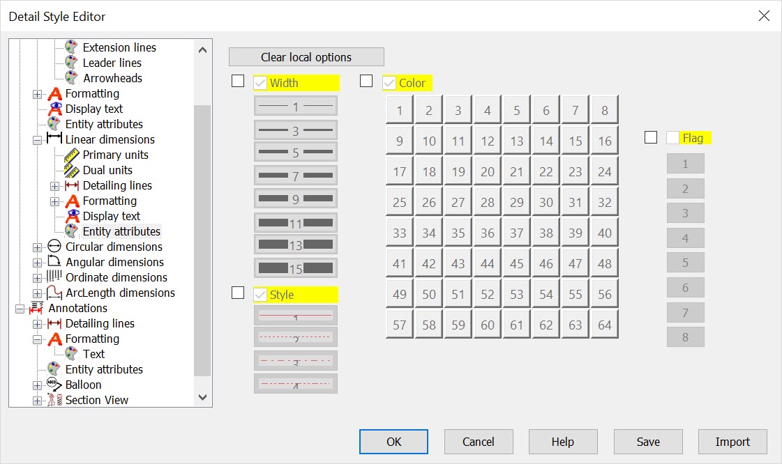
Below are the default (all cleared) attributes panes. The top shows the default settings of the Dimensions>Formatting>Text attrbutes (and Annotations>Formatting>Text) panes. The bottom shows the default for Dimensions>Linear dimensions>Entity Attributes> (and for all of the dimension detail entity subgroups: linear dimensions through arclength dimensions) panes.
After Changing Part SettingsNow you change the Part Settings toolbar as shown below and then create a second dimension.
The result is shown below. Notice that by changing the part settings, the dimension's lines are drawn using those attributes. This is because all the components of the dimension are using the system color. 
Setting Up Dimensions with Specific Attributes
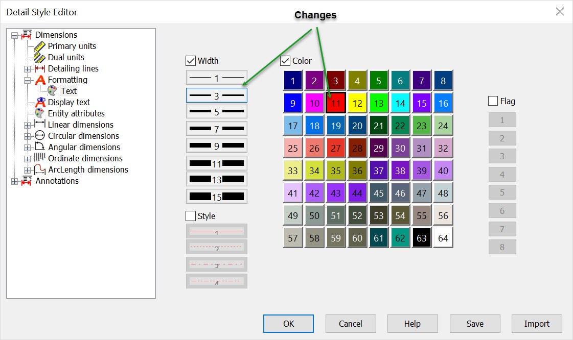
To set up dimensions so they always are created with specific attributes, make the settings on that attributes pane of the Detail Options dialog. For example, open the Detail Options dialog and go to the Dimensions>Detail attributes pane. Set the options here to make dimensions red with a line width of 3, as shown below. Creating dimensions now always makes red, 3-wide dimensions, regardless of the color and line width in the Part Settings toobar. Shown below is the current part settings and the created dimension. Notice that the part is set for blue, thin line entities. But the dimension is create with red, thick lines because that is what was set up in the entity attributes for dimensions. 
Returning to Previous Part SettingsAgain, notice the Part Settings toolbar: color 8, pen 1, line style 1, and line width 1. On the Detail Options dialog make the following settings on the Dimensions common pane. (For these examples, ignore the pen numbe,r since it does not affect directly screen appearance. So, the pen number settings are not shown in the figures below. The same principles do apply to pen number.)
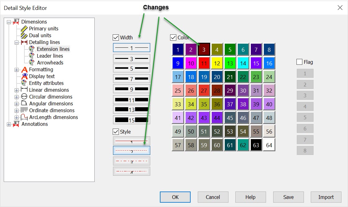
The Dimensions>Detailing lines>Extension lines pane is set as width 1, style 2 and color 3, as shown:
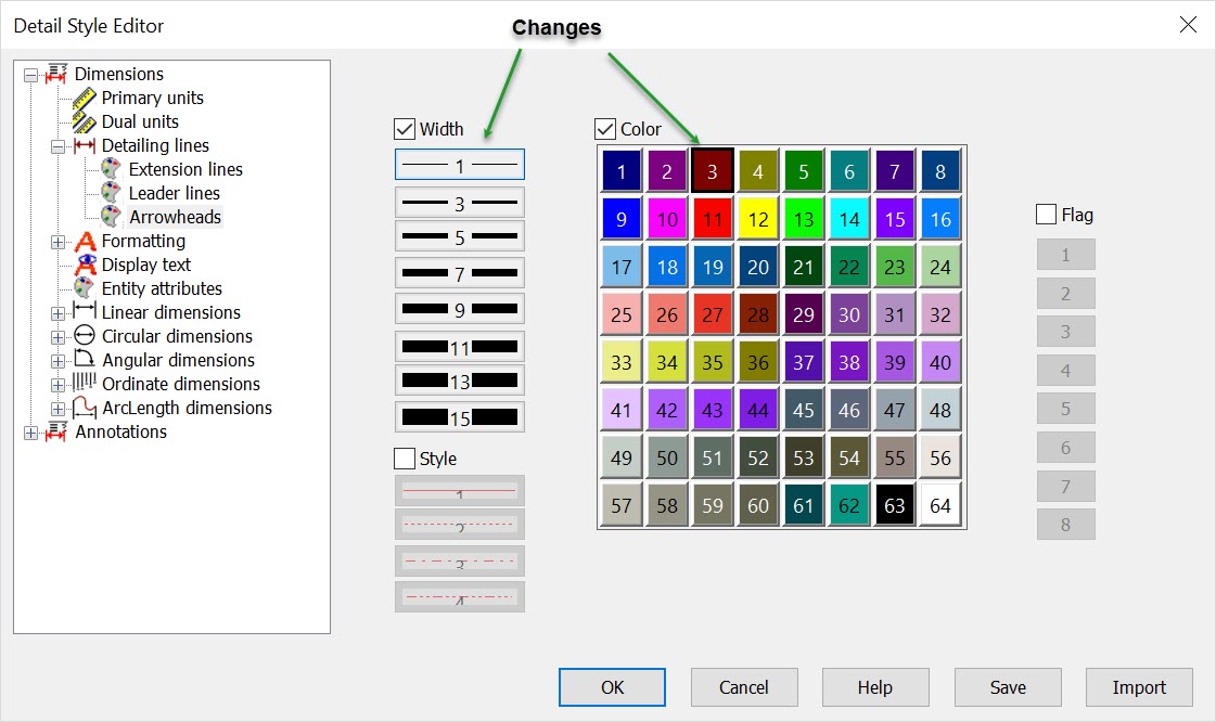
And, the common Dimensions>Detailing lines>Arrowheads pane is set as width 1 and color 3: Now, when you create another dimension above the line, the result is as shown below.
Notice that the text and the leader lines are using the attributes from the Dimensions>Detail attributes pane. But the extension lines and arrowheads are using the attributes from the Dimensions>Detailing lines>Extension lines and Dimensions>Detailing lines>Arrowheads. None of the elements of the dimension is using the settings on the Part Settings toolbar. This is because the attributes on the Detail Options dialog are overriding them, consistent with the table provided above. Clearing Common Options at This PointClear all the check boxes on the Dimensions>Detail attributes pane, and create a new dimension. The result is shown below. The extensions and arrowheads still are using their own attributes, but the leaders and text are now using the Part Settings attributes. The settings on the Detail Options dialog always override the settings on the Part Settings toolbar, when creating new detail entities. And, the settings on a local attributes pane on the Detail Options dialog always overrides the common options. 
Local Overriding Common
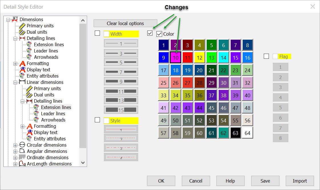
Now let us illustrate how a local attribute setting overrides a common attribute setting, again using linear dimensions as the example. Delete the top dimension in the figure above. Change Dimensions>Linear dimensions>Extension lines as shown below. That is, select the local-use boxes beside Color and Style. Clear the Style check box so that the Part Settings line style will be used. Select the Color check box and select color 10.
The result of creating a new dimension at this point is shown below. 
Continue the discussion of How Detail Style editor Affects Newly Created Detail Entities, by clicking Detail Settings Interaction with Detail Style Editor. |