Match Nurbs Surface Edges Dialog OptionsKeyCreator / Modify / Surface / Match Nurbs Surface Edges Dialog Options

Match NURBS Surface Edges Dialog Options
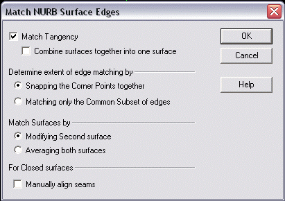
The Match NURBS Surface Edges dialog appears when Match Edges is selected from the Modify>Surface submenu.
Dialog Options:

Match Tangency
This box is checked by default. This means that the surface edges will match with G1 (normal) continuity across the common edge. (The surfaces will always match tangentially along the common edge since they both share the exact same edge curve). If this box is unchecked, then the surface edges will match with G0 (position) continuity across the common edge.
Determine extent of Edge Matching by
The extents of the edges to be matched may have to be determined to handle the cases where the surface on the left is larger than the surface on the right, or the surface edges overlap by some distance. (This only applies to Open surfaces and the setting has no effect on closed surfaces)
-
Snapping the Corner Points together – Use this option when the intent is simply to match the entire length of each surface edge with the other (hence bringing the corner points of the two surfaces along the common edge together). Typically you would want this when the surface edges nearly matched but with a small gap, however it could also be used to force a smaller edge to take on the shape of a larger edge or vice versa.
-
Matching only the common subset of edges – Use this option when the surface corner points would not meet because one surface is larger than the other and it is not the intent to match the entire length of the edge. In this case, the portion of each surface that does actually meet is determined automatically and the surfaces are broken along a line of constant parameter to produce two surfaces that do meet each other along the entire length of the common edge. The portions that are broken off become new surface entities.
Match Surfaces by
When matching the edges of surfaces you can force one surface to match the edge and tangents of the other surface (modifying one surface and keeping the other unchanged), or you can choose to average the surface edges together (modifying both surfaces).
-
Modifying second surface – The second surface selected is the one to be modified to match the first surface selected. The first surface is not modified.
-
Averaging both surfaces – Both surfaces are modified equally. The final common edge will be half way between each surface edge and the cross tangents will be averaged.
For Closed Surfaces
When two smoothly closed (a.k.a. Periodic NURBS) surfaces are selected, the seams of the surfaces must be aligned properly or the resulting matching of edges might cause the surfaces to twist.
-
Manually align seams - The seam of a closed surface is the longitudinal edge along which the surface cross curves start and end. Seam alignment is automatic and most of the time there will be no need to manually align the seams, however if the result produces an unwanted twisting effect, then if you check the box, you will be see a rubber band line anchored at the seam location of the first surface, and you will be prompted to indicate the desired seam position on the second surface edge. The optimal position is usually one that is closest to and most perpendicular to the first seam. This setting will have no effect if the surfaces selected are not closed. If you attempt to match an open edge with a closed edge, you will receive the following error message "Unable to match edges if one is open and one is closed".
How it Works:
Because the Surface Edge matching function is designed and intended to work only on untrimmed iso-edges of NURB surfaces, the following limitations exist: If you select a surface that is not a NURB surface, it will be converted to a NURB automatically and the result will be a NURB. If you select a Trimmed surface (face) and the underlying surface is modified, then the trimming information will be lost. If you select a face that is stitched into a larger body, it will be unstitched automatically.
The surface edge matching works by making the surfaces compatible with one another through a process of degree elevation, knot parameter insertion, control point snapping and tangent vector length re-proportioning. Any change in surface shape is restricted to the first row of patches closest to the common edge. It will handle any combination of surface degrees. For example, if a cubic (degree 3) surface is matched to a quintic (degree 5) surface, then the result will be that both surfaces now have degree 5. The accuracy of edge matching is guaranteed to produce a zero gap and parallel normals/tangents (to double precision accuracy), but the results can always be verified using the Tools > Verify > Deviations > Edge to Edge function.

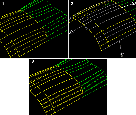
Above > This figure illustrates two surfaces which have a .0003 inch gap but a 16 degree angular difference between the normals.
After selecting the surfaces, they are redrawn temporarily with flowlines at knot values (patch boundaries). This is so that you can see the full extents of each underlying surface. You are then prompted to indicate the edge on each surface to be matched. Temporary vectors are drawn at the mid point of each edge pointing away from the surface. As you move the cursor near the vectors, they highlight indicating the chosen edge. Specify the edge for each surface
In this figure, both surfaces were modified by averaging the tangents. Notice how the flowlines now line up exactly. This is not a necessary condition for a perfectly matched edge, but will happen if both surfaces are averaged.

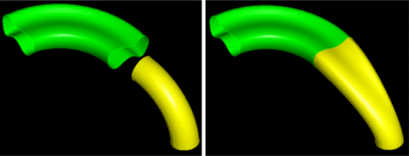
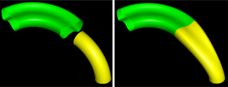
Above > In this figure, two closed surfaces with vastly different cross sectional shapes are to be matched. Automatic seam alignment is performed. yellow tubular surface is forced to match the shape of the green surface.
-
Surface edge matching is the process of forcing two surfaces to share a common edge. More specifically, it provides a capability for matching the iso-edges of two NURB surfaces so that they match with both positional and tangential continuity to double precision accuracy.
-
Iso-edges are defined as the four outer edges of a four sided untrimmed NURB surface. This function does not attempt to match the surface geometry along trimmed edges. That is the subject of "Stitching". Surface edge matching differs from Stitching as follows:
-
Stitching - is a topological operation that joins faces together along edges which are similar but perhaps not exact, by inserting topology information (for example tolerant edges/coedges which carry local tolerance information describing the size of the gap between the edges). Stitching does not alter the underlying geometry of the surfaces.
-
Surface edge matching - is a purely geometric operation and ignores the topology (trimming curves of a face). It modifies the underlying NURB surface geometry in such a way as to force the surfaces to exactly share a common edge and provides a perfectly air tight joint as well as providing for perfect surface normal (G1) continuity across the common edge. If you desire to stitch these matched surfaces together into larger sheets, then the stitching will produce precise (exact) edge topology instead of tolerant topology.
Surface Edge Matching also provides the capability of combining two NURB Surfaces together into a single larger surface, (providing that you have chosen to match with tangential continuity). In addition to being surface normal (G1) continuous, the resulting surface will be Parametric (C1) continuous along the common edge where they were joined together. This means that the parameter value has continuous speed across patch boundaries and is an important consideration for the success of geometric algorithms such as intersections.

Above > This figure demonstrates two surfaces for which only a portion of each edge overlaps the other. By choosing the option "Matching only the common subset of edges" we can match the portions that make sense to match. After matching the subset of the edges that actually overlap, the red surfaces are now separated off as individual surfaces.
|