KeyCreator / Verify / Verify Face Dialog OptionsVerify Face Dialog OptionsThe Verify Face Information dialog appears after you select the face you want to examine, using the Face feature available from the Tools>Verify submenu. 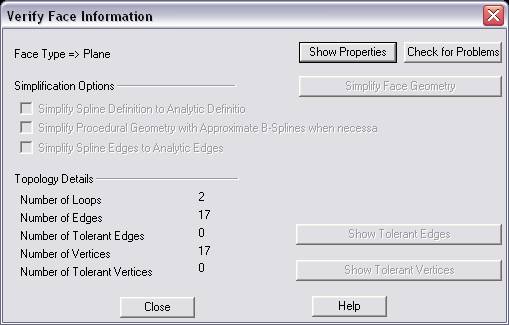
Description of Entries in the Dialog:What is the geometry that defines the face?The face geometry can be defined by a Plane, Cone, Cylinder, Sphere, Torus, Exact Spline or various Procedural Splines. Planes, Cones, Cylinders, Spheres and Tori are classified as analytic geometry since they can unambiguously be represented by a simple algebraic formula. Exact Spline geometry is synthetic and is an approximation or interpolation of data points defining the geometry of the face Procedural splines are a special type of spline geometry. This type of geometry is typically created by a specific modeling operation. For example, ”r;Rolling Ball Blend” or ”r;Vertex Blend” face geometry typically gets created during a blending operation. Show PropertiesSelecting this button will cause the Verify Face Information dialog to temporarily disappear and a dialog listing the properties of the specific face type will appear. Below is a list of the data that is displayed for each face type:
Check for ProblemsSelecting this button will cause the function to check the face for any problems. A dialog will be displayed with the problems found with the face (if any). Simplification Options:These options allow you to replace spline definitions of the face geometry with analytic definitions when possible. There are 3 options available: Simplify Spline Definition to Analytic DefinitionThis option will become enabled if the face geometry is either an exact spline or any one of the different procedural splines. Checking this option ON will cause the function to attempt to replace the spline definition with an analytic definition. Simplify Procedural Geometry with Approximate B-Splines when necessaryThis option will become enabled if the face geometry is any of the different procedural splines. Checking this option ON will cause the function to replace the procedural spline with an exact spline if simplification to an analytic definition proves difficult. Simplify Spline Edges to Analytic EdgesThis option will become enabled if the face geometry is either an exact spline or any one of the different procedural splines. Checking this option ON will cause the function to attempt to additionally replace the spline definition of the edges of the face with an analytic definition. Topology Details:Number of LoopsThe number of loops on the face is displayed. A loop represents a connected portion of the boundary of a face. Each loop determines the portion of the surface that is inside the face and the portion that is outside. Number of EdgesThe number of edges on the face is displayed. An edge constitutes the boundary one or more faces. It is bounded by two vertices. Number of Tolerant EdgesThe number of tolerant edges on the face is displayed. If tolerant edges exist on the entity the ”r;Show Tolerant Edges” button will be enabled. Selecting the button will cause the results dialog to temporarily disappear. The tolerant edges on the face will be highlighted. You may select any one of the highlighted edges to get its tolerance. Click on ACCEPT in the Conversation Bar to model temporary geometry indicating the tolerant edges. Clicking either BACK or ESCAPE will un-highlight the sliver faces and return you back to the results dialog. Number of VerticesThe number of vertices on the face is displayed. A vertex is the corner of a face and refers to a point in 3D space. Number of Tolerant VerticesThe number of tolerant vertices on the face is displayed. If tolerant vertices exist on the entity the ”r;Show Tolerant Vertices” button will be enabled. Selecting the button will cause the results dialog to temporarily disappear. Temporary points will be drawn to indicate the tolerant vertices on the face. Click on ACCEPT in the Conversation Bar to leave points in the part. Clicking either BACK or ESCAPE will un-highlight the sliver faces and return you back to the results dialog. |