Part Splitter WindowKeyCreator / View / Control Bars / Part Splitter / Part Splitter Window
Using this function:
The Part splitter window is a dialog box with tabs whose panes are described below. You can control the display of the Part splitter window by clicking View>Control Bars and then clicking Open Part Splitter, Close Part Splitter or Toggle Part Splitter. Or, as shown in the figure below (which shows the workspace), you can drag it open or closed. Once opened you are presented with a series of tabs explained below. Levels Tab:The Levels tab of the Part splitter window displays the level tree for the current part, and allows you to set and change a variety of level attributes. By clicking in the appropriate cell, you are able to modify the information contained in the Level List Window. This can also be accomplished through the right-click context sensitive menu (left click on the level and right click to get context menu.) The header cell title blocks indicate the focus of each of the columns in the Level List. You can modify the order in which the levels are displayed by clicking on each of the blocks. For expanded information regarding the Levels interface and Levels modification features, see Using the Levels Tab View> Level.
Part References Tab:The Part References tab displays the reference tree for an assembly. Through this dialog, you can edit the parameters for references in the part. For more information on the available assemblies features, see Using Assemblies.
Level Sets Tab:
The pane that appears when you click the Level Sets tab allows you to control which levels are displayed through references to that part. Because there can be multiple level sets, different references can display different levels using different level sets.
Features Tab:The Features tab displays a tree of the discovered features in the current part (such as Holes, Pockets, Chamfer, Boss for example.) When a feature is selected on a model using the Edit>Entities>Generic Edit function, this tree is displayed immediately. Through the tree, you can view and edit all of the available parameters for the selected feature. When a feature is selected in the tree, it automatically highlights on the model for easy recognition (unless that feature is suppressed). To populate the feature list use Create>Solid Feature>Discover Features. To modify the available parameters for a selected feature, click on the feature to expand its tree. Select a parameter and click on the downward facing arrow for a list of available options.
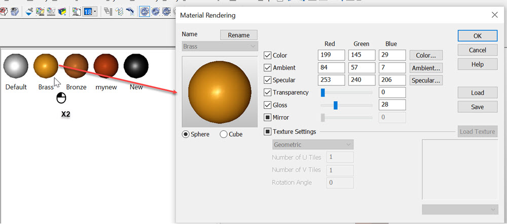
Materials Tab:Change Material Properties
The Materials tab allows you to double-click a sphere in the Materials pane to display the Material Rendering dialog box. Define the desired property on this dialog and click OK. Then the sphere has that property: Add Material to Object
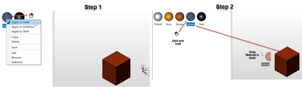
Right click a sphere and choose the desired selection from the drop-down (Apply to Solid, Apply to Solid Face, Apply to Shell) Then drag the sphere onto the part thereby applying the property to the highlighted entity: Add Material
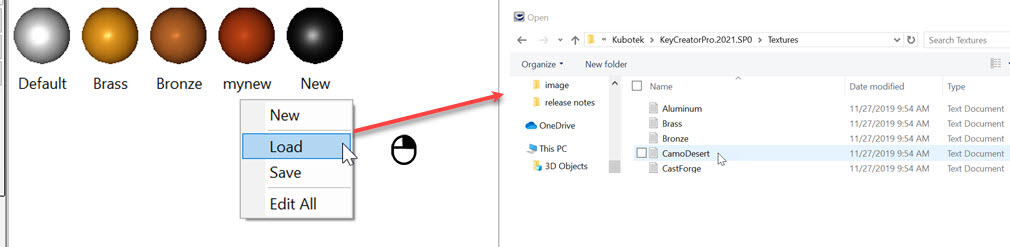
To add a material right click in the Materials pane and choose New and name the material. If it is a listed material in the Textures folder within KeyCreator, simply use the name of the text file (an example would be the glass.txt file , simply name the new material glass and select load and choose the glass.txt file.) The context menu also allows you to load material from the KeyCreator>Texture folder by choosing the Load Option: Additional Notes on Materials:
Save Current Material/Materials — A save can be done to entire set currently loaded, (right click in Materials list area and choose save) or selected Materials, (right click on material name and choose Save).
Duplicate Names — Any duplicate names will be listed with a numerical increment, (NewMaterial.txt, NewMaterial1.txt...) Choose Edit to re-name and Save. Edit All — Used to load all currently listed materials into the Materials Rendering Edit dialog. OK updates selected material in splitter window. Save will save selected material to a material .txt file. Load will open existing file to be edited and New will create a new material in material part splitter. Context Menu Unset — Right click in materials window and choose Unset will remove materials from selected faces/solids. Material List organize — Materials are organized horizontally and by splitter window width. Left click select a material and drag to re-arrange listing: 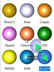
Material Icon Context Menu Selection Function — Brings up USM, (Universal Selection Menu) in conversation bar. Verify Material — Use Verify>Entity and pick solid/Face to list material information: 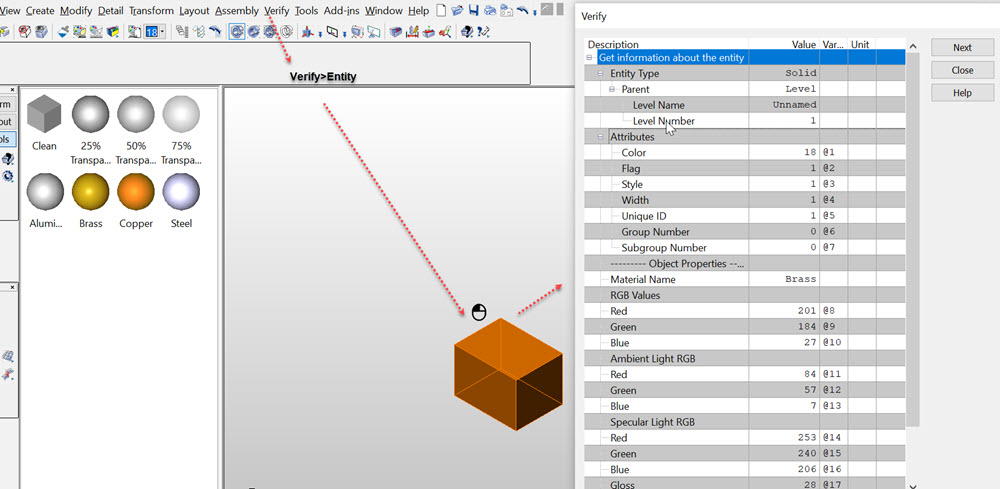 Drawing Instances Tab (Layout Mode):See Layout Instance Tab. |