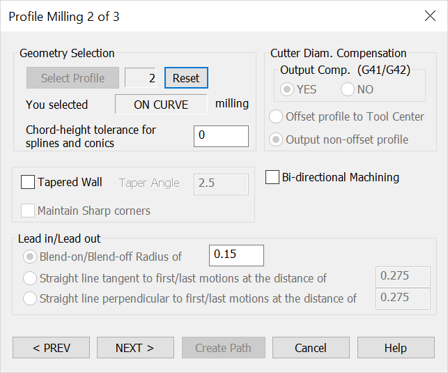
2ND Profile Milling DialogKeyCreator / Tools / Machinist / 2D / 2ND Profile Milling DialogThis dialog appears when you click the Next button on the first Profile Milling dialog. By default, all of the settings in this second dialog are unavailable. You must first select the profile geometry. To do this, click the Select Profile button, and follow the menu options that appear on the Conversation Bar. For a list of these steps, see the 2D Profile/Contouring Overview segment. Once you have selected the profile, and after you have configured the dialog settings that appear, click the Next button to move on to the next dialog.
The 2ND Profile Milling dialog after the Profile geometry was selected: Geometry SelectionThe information relative to the profile geometry you have selected appears here. Click the Reset button to return the counter to 0. After clicking Reset, you will be required to re-select the profile geometry. Specify a chord-height tolerance for splines and conics. Cutter Diameter Compensation
Tapered WallWhen selected, you are able to specify an angle value for the taper. Lead In / Lead OutThe settings under this heading are used to define the manner in which the tool moves up to and away from the wall, to eliminate dwell marks and to properly apply the cutter dimension compensation. These motions are not part of the contour.
|