KeyCreator / File / Import / Working with Import Files / Common Import Options
When the Options button is selected from the File dialog when importing, opening or batch-translating a file or files, a dialog appears with two tabs. The first is specific to the method of translation. The second, Common Import Options, contains options import methods share. An example of the Common Import Options pane appears below (Unigraphics import).
Dialog Options:
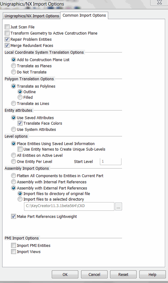
Scan File Only
This option is available for the following translators: SolidWorks, Inventor, CATIA V4, CATIA V5, Pro/E, Unigraphics, STEP, Parasolid, IGES.*Construction_ Select to scan the file for basic information instead of having to wait until the translation completes to get these details.
Transform Geometry to Active Construction Plane
When this option is enabled (checked), the imported geometry will be transformed to the current active Construction Plane. This option is enabled by default.
Repair Problem Entities
It is strongly recommended that you select this option. It corrects problems in the file being translated. Some of the conditions that it addresses are as follows:
-
Elimination of duplicate or overlapping vertices, tiny edges and silver faces
-
Repairing of badly defined spline surfaces
-
Simplifying spline faces and edges to analytic definitions
When less precise entities from other systems are translated into the high precision KeyCreator modeling environment, typically the translated entities show gap errors. This option also corrects the difference in precision between the entities in the file being translated and KeyCreator by tolerizing the translated entities.
Local Coordinate System Translation Options
These options handle the translation of local coordinate systems.
-
Add to Construction Plane List - When selected (default), the translated local coordinate systems are added to the part's list of construction planes.
-
Translate as Planes - When selected, local coordinate systems are translated as KeyCreator plane entities.
-
Do Not Translate - When selected, local coordinate systems are not translated.
Polygon Translation Options
This option is available for the following translators: STEP, Parasolid, SolidWorks, Autodesk Inventor, CATIA V4, CATIA V5, Pro/Engineer, Unigraphics. Controls how triangular entities (three planar lines forming a closed loop) are translated into KeyCreator
-
Convert as Polylines – Results in triangle entities being converted as KeyCreator polylines. You can select whether these polylines are represented as outlines or filled
-
Convert as Lines – Bursts the triangle entity into three lines while importing it into KeyCreator
Entity Attributes
-
Use Saved Attributes (default) - When selected, the RGB color attributes of the entities in the file are translated. When this setting is enabled, you can also elect to translate face colors.
-
Use System Attributes - When selected, the imported entities take on the current system attributes.
-
Translate Face Colors – When this setting is enabled, you can also elect to translate face colors.
Level Options
-
Place Entities using Saved Level Information (default) - When selected, layer information (if available) is translated. If the file was exported from KeyCreator, the level structure and level descriptor are preserved upon import.
-
Use Entity Names to Create Unique Sub-Levels – When selected, sub levels will be created from the entity names in the import file.
-
Place Entities on Active Level - When selected, the imported entities are placed on the active level.
-
One Entity Per Level – When selected, levels will be dispersed so that no more than one (1) appears on a level. Specify the level number on which the first entity will be placed.
Assembly Import Options
The options below are available for all translators except Catia v4.
-
KeyCreator Assembly with Internal Part References – Creates a KeyCreator assembly in the current/active part of the open .ckd file. The assembly references other (new) parts in the same .ckd file.
-
KeyCreator Assembly with External Part References – Creates a KeyCreator assembly in the current/active part of the open .ckd file. The assembly references parts in other (new) .ckd files. The two options below allow you to choose the directory in which to place a converted .ckd file with external part references. These two options are unavailable when you select either Flatten All Components to Entities in Current Part Assembly with External Part References
-
Import files to directory of original file – Place the file in the directory where the original file resides.
-
Import files to a selected directory – Place the file in the directory that you select, using the provided browse button. The default is the CKD directory path.
-
Make Part References Lightweight – When selected (Default), part references are made lightweight.
PMI Import Options
-
Import PMI Entities – Any product manufacturing information such as annotation and geometric tolerance data will be imported. The detail data such as geometric tolerances will convert to general detail entity types (not seen as an edit able geometric symbol.)
-
Import View – imports the product manufacturing information view matrix which can be seen in the display view list.
|