|
KeyCreator / Modify / Solid Face / Deform Faces Dialog The Deform Face Options dialog box appears when you select Modify>Solid Face>Deform Face and click the desired face/faces on the model. Deform Faces Dialog Options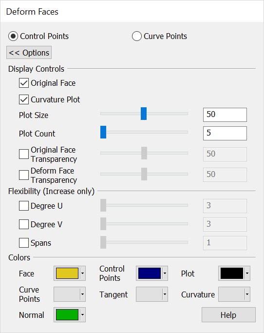 Control Points/Curve PointsChoose the point deform method to modify faces. Control points are coefficients on the Nurbs curve, increasing the Degree or spans between control points will increase control points. Curve points are simply points on the curve constrained by the point, tangency and curvature (Degree and Span do not apply.) Left clicking on a point will present a DyanHandle which can be used to modify the point positioning. Right click on a given Dynahandle axis will bring up a context menu with additional options for modifying the point on the curve. Display ControlsOriginal Face- Choose to display original face alongside the deform face. Curvature Plot- When checked will display a curve plot of specified plot size and plot count. The Plot is a radius representation of the surface curves. the Plot size controls how large the curvature plot will be displayed while the plot count controls the amount of segments for the curvature plot. Original/Deform Face Transparency- Will control the amount of transparency for visualization of internal geometry within the model in both a positive or negative direction. Use the slider to adjust or enter values up to 100. FlexibilityDegree and span can be controlled in the positive direction only and will not effect the Curve Point method. Increase control points with the Degree U-V slider/ Spans slider or enter a desired value. ColorsUse the color pallet menu to define unique colors to the Deform Face options for better visualization. |