Verify Body Diagnostic ResultsKeyCreator / Verify / Verify Body Diagnostic ResultsThe Verify Body / Sheet Body Results dialog appears after you select a body to verify using the Tools>Verify>Body function. Note: Solids and sheet bodies imported by the following translators: CATIA V4, CATIA V5, Pro/E, Unigraphcs, SolidWorks, Inventor, STEP, Parasolid, IGES are marked. Consequently, a message like the following may appear on the Verify Solid/Sheet Body Results dialog box, above Diagnostic Results: ”This solid was translated into Version 6.0.0 (0079) from a Parasolid file.” This information can assist Technical Support. 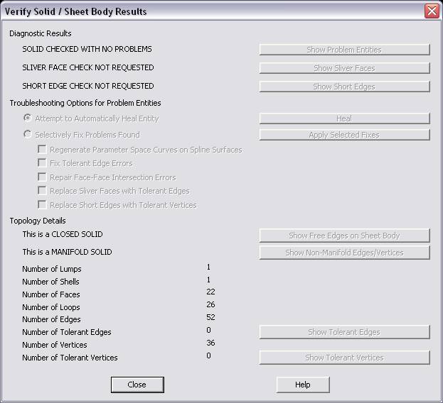
Diagnostics Results:Did the solid/sheet body check with problems?If problems were found in the selected body, the ”Show Problem Entities” button will be enabled. Selecting the button will cause the results dialog to temporarily disappear. Temporary wireframe geometry will be drawn over the edges or vertices of the entity that either showed problems or are associated with the problems found. The color of problem faces is set to the Error color selected on the Colors/Attributes pane of the Properties dialog box (File>Properties>Colors/Attributes). Click on ACCEPT in the Conversation Bar to leave the temporary geometry in the part. Back or Escape will erase the temporary geometry and take you back to the results dialog. A notepad window will open up listing the internal IDs of the entities and the error message associated with them. While there is no function in the product currently that will allow you to search for an entity using the ID, advanced users may write CDEs or KXL scripts that can parse the text file and highlight the entities (as an example). Were sliver faces found?If sliver faces were found in the selected body, the ”Show Sliver Faces” button will be enabled. Selecting the button will cause the results dialog to temporarily disappear. The sliver faces on the entity will be set to blue (R=0, G=0, B=255). Click on ACCEPT in the Conversation Bar to model temporary geometry indicating the sliver faces. Clicking either BACK or ESCAPE will un-highlight the sliver faces and return you back to the results dialog. Were short edges found?If short edges were found in the selected body, the ”Show Short Edges” button will be enabled. Selecting the button will cause the results dialog to temporarily disappear. The short edges on the entity will be set to color 8 on the Entity Color Palette (File>Properties>Colors/Attributes). Click on ACCEPT in the Conversation Bar to model temporary geometry indicating the short edges. Clicking either BACK or ESCAPE will un-highlight the sliver faces and return you back to the results dialog. Troubleshooting Options for Problem Entities:If problems were found with the selected solid or sheet body, the troubleshooting options will become available. There are two main choices that can be made: Attempt to Automatically Heal EntitySelecting this option will cause the ”Heal” button to be enabled. The function will attempt to automatically fix problems with the geometry. This option is not guaranteed to fix all the problems with the geometry but may help alleviate some of them. Once the healing process completes, the entity will be re-checked for errors. The results dialog re-appears with the information as pertinent to the healed entity. Selectively Fix Problems FoundSelecting this option will cause one or more of the check boxes listed below it to become enabled depending on the types of problems that were found. Selecting one or more of the enabled check boxes will cause the ”r;Apply Selected Fixes” button to be enabled. You may then select the button to apply the specific fixes to the geometry. As with the first option, once the fixes are applied, the entity is re-checked for errors. The results dialog re-appears with the information as pertinent to the modified entity. Note that the list of fixes is not all-inclusive and is a subset of what ”r;healing” can accomplish. This option is geared towards addressing specific problems in a model as opposed to healing the entire model. A combination of these options and other geometry reconstruction tools available in the product may be best suited to repair problems in the geometry. Regenerate Parameter Space CurvesChoosing this option causes any existing parameter space curves to be deleted from the selected entity and to be recreated from scratch. Parameter space curves are the parameter space representations of spline face trimming curves. They do not apply to analytic faces such as planes, cones, cylinders, spheres and tori. Generally, messages such as "pcurve location != coedge location" (seen in the notepad window when viewing problem entities) are an indication of such a problem. Repair Self Intersections in SolidThis option may only become enabled if you had opted to ”Check for Face-Face Intersection Errors” in the options dialog. Choosing this option causes the function to attempt to repair invalid self-intersections between two faces in the solid. This option applies only to solids and not to sheet bodies. Fix Tolerant Edge ErrorsThis option will attempt to fix any tolerant edge errors in the entity. Generally, errors associated with messages such as ”TCOEDGE and TEDGE geometry appear to be incompatible”, ”Geometry at start of TCOEDGE and TEDGE appear inconsistent” and ”Geometry at end of TCOEDGE and TEDGE appear inconsistent” (seen in the notepad window when viewing problem entities) are the categories of problems that this option tries to address Replace Sliver Faces with Tolerant geometryIf this option is checked ON, any sliver faces that were found will be replaced with tolerant edges Replace Short Edges with Tolerant verticesIf this option is checked ON, any short edges that were found will be replaced with tolerant vertices Topology Details:Is the selected entity a closed solid or an open sheet body?If the entity is a sheet body, the ”Show Free Edges” button will be enabled. Selecting the button will cause the results dialog to temporarily disappear. The free edges of the sheet body will be set to color 6 on the Entity Color Palette (File>Properties>Colors/Attributes). Click on ACCEPT in the Conversation Bar to model temporary geometry indicating the free edges. Clicking either BACK or ESCAPE will un-highlight the sliver faces and return you back to the results dialog. Is the selected entity a manifold solid (or sheet body) or a non-manifold solid (or sheet body)?If the solids or sheet body selected is non-manifold then the ”Show Non-Manifold Edges/Vertices” button will be enabled. Selecting the button will cause the results dialog to temporarily disappear. Temporary geometry will be drawn to indicate the non-manifold edges and vertices of the solid or sheet body created in color 15 on the Entity Color Palette (File>Properties>Colors/Attributes). Click on ACCEPT in the Conversation Bar to leave the temporary geometry in the part. Clicking either BACK or ESCAPE will un-highlight the sliver faces and return you back to the results dialog. Number of LumpsThe number of lumps in the solid or sheet body is displayed. A lump represents a bounded, connected region in space. A solid or sheet body can be composed of one or more lumps. Number of ShellsThe number of shells in the solid or sheet body is displayed. A shell is a connected set of faces in the solid or sheet body. Number of FacesThe number of faces in the solid or sheet body is displayed. A face is a trimmed portion of a single geometric surface. One or more loops of edges make up the boundary of the face. Number of LoopsThe number of loops in the solid or sheet body is displayed. A loop represents a connected portion of the boundary of a face. Each loop determines the portion of the surface that is inside the face and the portion that is outside. Number of EdgesThe number of edges in the solid or sheet body is displayed. An edge constitutes the boundary one or more faces. It is bounded by two vertices. Number of Tolerant EdgesThe number of tolerant edges (if any) in the solid or sheet body is displayed. If tolerant edges exist on the entity the ”Show Tolerant Edges” button will be enabled. Selecting the button will cause the results dialog to temporarily disappear. The tolerant edges on the entity will be set to color 4 on the Entity Color Palette (File>Properties>Colors/Attributes). You may select any one of the highlighted edges to view its tolerance. Click on ACCEPT in the Conversation Bar to model temporary geometry indicating the tolerant edges. Clicking either BACK or ESCAPE will un-highlight the sliver faces and return you back to the results dialog. Number of VerticesThe number of vertices in the solid or sheet body is displayed. A vertex is the corner of a face and refers to a point in 3D space. Number of Tolerant VerticesThe number of tolerant vertices (if any) in the solid or sheet body is displayed. If tolerant vertices exist on the entity the ”Show Tolerant Vertices” button will be enabled. Selecting the button will cause the results dialog to temporarily disappear. Temporary points will be drawn in color 4 on the Entity Color Palette (File>Properties>Colors/Attributes) to indicate the tolerant vertices on the entity. Click on ACCEPT in the Conversation Bar to leave the points in the part. Clicking either BACK or ESCAPE will un-highlight the sliver faces and return you back to the results dialog. |