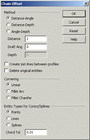
KeyCreator / Transform / Chain Offset / Chain Offset Dialog OptionsChain Offset Dialog OptionsThe Chain Offset dialog box contains the following selections for chain offsets: Dialog Options:
MethodThe method is the process the program uses to specify the Offset Distance, Draft Angle, and Offset Depth. For example, if you know the distance and depth at which you want the offset to be created, you can input those values and the Draft Angle will be determined for you. The Offset Distance is the distance at which you want the offset created from the original geometry. The Draft Angle is the angle that is drawn from the original geometry to the offset geometry. The Offset Depth is the depth at which you want the offset created from the original geometry. A positive depth indicates that the offset lies on a plane parallel to the construction plane at a distance "depth" from the construction plane in the direction of the construction view Z axis. When creating offsets, it is important to keep the following in mind:
The following options are available under Method in the "Chain Offset" dialog box:
Create join lines between profiles (check box)Activates or deactivates join lines. If you activate Join lines, the end points of the original geometry connect to the end points of the corresponding entities in the offset chain. Delete original entities (check box)Selecting this check box will delete the entities selected for chain offset after chain offset entitites are created. CorneringThe options under the Cornering heading in the "Chain Offset" dialog box allow you to select how to display offset corners when consecutive, non-intersecting offset entities are created. The available cornering options are: Linear, Fillet Arc, and Fillet Chamfer.
Entity Types for Conics/SplinesWhen working with conics, splines, and arcs that are out of view, you must specify whether the offset will be represented by Points, Lines, or Splines.
Chord ToleranceA Chord Tolerance specifies the maximum distance between the true mathematical offset and the approximating offset of a conic, spline, or arc skewed to the construction plane. The smaller the chord height tolerance, the closer the approximating offset is to the true offset.
OKAccepts the information in the dialog box and allows you to select the entities to chain. RESETWhen selected, whatever values you may have entered will be lost, and the settings will revert back to their previous values. |