Feature Control Frame Dialog Frame TabsKeyCreator / Detail / Symbol / Feature Control Frame / Feature Control Frame Dialog Frame Tabs
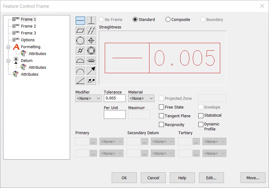
The Frame 1, Frame 2, and Frame 3 dialog pages allow different options for the frame type that you are able to display with the symbol being created. For instance, only the Standard frame type is available for Frame 1. No Frame, Standard, and Composite are options for Frame 2, and none are available for Frame 3.
Available Frame Types:
-
No Frame – When selected, no frame will be displayed with the symbol you are creating.
-
Standard – When selected, the symbol you create will be displayed with a standard frame.
-
Composite – This option will create a symbol with one geometric characteristic symbol, followed by individual segments for each tolerance and datum field, one above the other.
-
Boundary (Surface Profile symbol only) – This was a new concept for ASME Y14.5M-1994. This option creates a symbol that combines positional tolerances with profile tolerances. This is useful when it is necessary to control the boundary and position of a non-cylindrical feature.
Modifier
There are several modifiers available from the Modifier drop-down menu, shown below.

Tolerance
Enter a tolerance value for the symbol, to appear after whatever modifier is selected, if one is chosen at all.
NOTE: You can enter the Unequally Disposed symbol ( |UED ) between values if needed:
Per Unit
Per Unit applies to both Flatness and Straightness styles. This setting will be inactive when it does not apply to the symbol selected. When active, you are able to enter a per unit tolerance setting in the editable field.
Material
Specify a material to be displayed in the Geotol symbol being created. The available material options are listed and explained below:

-
MMC - Maximum Material Condition means the maximum amount of material permitted by the tolerance size dimension for that feature. For internal features such as holes and slots, MMC is the condition where these features are at their minimum allowable size. For shafts, bosses, and other external features, MMC is the condition where these features are at their maximum allowable size.
-
RFS - Regardless of Feature Size, when applied to positional tolerance for circular features, requires the axis of each feature to be located within the specified positional tolerance regardless of the size of the feature. RFS imposes a closer control of positional tolerances than MMC.
-
LMC - Least Material Condition means that the feature in the part contains the minimum amount of material permitted by its tolerance size dimension. Specification of LMC also requires perfect form at LMC.
Maximum
Where the feature departs from its MMC size, a perpendicularity tolerance is allowed which is equal to the amount of the departure, up to .002 maximum (ANSI Y14.5-1973).
Miscellaneous Checkboxes
The following checkbox settings are available from the Frame 1, Frame 2, and Frame 3 pages, depending upon what is specified for each.
-
Projected Zone - Used where the variation in perpendicularity of a hole might cause a fastener to interfere with a mating part.
-
Tang. Plane - (ASME Y14.5M-1994 Standard Only) The Tangent Plane modifier is new to the ASME Y14.5M standard. It is used when it is desirable to control a feature surface established by contact points on the surface.
-
Free State - (ASME Y14.5M-1994 Standard Only) The Free State modifier is new to the ASME Y14.5M-1994 standard. When used in a control frame, it ensures that when the part is being inspected, it will not be restrained.
-
Reciprocity - This is the symbol for the principle of reciprocity, an ISO standard.
-
Envelope - This checkbox is available for ISO, DIN, JS, and KS standards (as specified in the Options tab of this dialog). Enabling this checkbox adds an Envelope modifier to the symbol. This indicates that all points on the surface of a feature lie within the limits defined by its MMC (Maximum Material Condition). Any surface variations due to flatness, parallelism, etc. must reduce to zero as the size approaches MMC.
-
Statistical - (ASME Y14.5M-1994 Standard Only) Statistical Tolerance is new to the ASME Y14.5M-1994 standard. The symbol indicates that statistical process controls should be used in the production of the part referenced. The ASME Y14.5M-1994 standard requires that a note be placed in the drawing whenever the ST modifier is used. The note text will vary depending on the specific usage of the modifier, so you should refer to the ASME Y14.5M-1994 standards documentation for the specific wording of the note.
|