Cut Trim PlanesKeyCreator / View / Cutting Plane / Cutting Plane
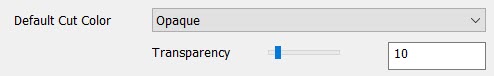
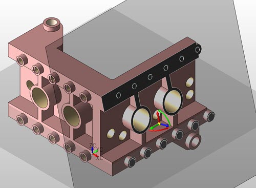
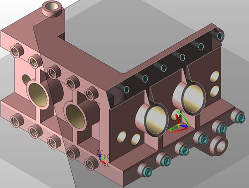
Use this function to create and manipulate cutting planes dynamically. You define cut Trim planes using the Conversation Bar shown below. This contains buttons for standard plane definitions and the world coordinate system (XY, XZ and YZ). Use the 2 Auto or 3 Auto buttons to create using the DynaHandle two cutting planes or three cutting planes automatically. To change the planes color representation or set a transarency, (a % see through of trim plane) use File>Properties>Display Colors>Cutting Plane section:
NOTE: Note: You can create a cutting plane only in model mode. 
You can also control the positioning and orientation using the DynaHandle object which is attached to the center of the plane.
Trim If you click the Trim button on the Conversation Bar, the following dialog appears, which allows you to:
|