|
KeyCreator / Tools / Machinist / 2D / Face Mill

This creates a 2 axis tool path of parallel zig-zag passes using the maximum rectangular extents of selected edges. This is often used to face or clean up the top of a flat surface. Using this FunctionBelow are general steps to complete a 2D Face Mill. For greater details on any of the steps refer to the KeyMachinistRefManual.pdf .
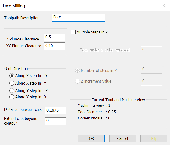
Face Mill Dialog Tool Path DescriptionEnter a descriptive name (optional.) Useful for identifying tool path later in the process. Do not use numeric values in the beginning entry for description name. X/Y/Z PlungeZ plunge- Distance for rapid Z motion. XY plunge- Distance from initial point for plunge feed rate. Multiple Steps in Z OptionOption to make additional Z passes using the following values, otherwise a single pass is made at selected location. Total Material to be Removed - Total Material to be removed value used in number of passes calculation. Number of Steps in Z - Number of additional passes to be made in the Z direction based on increment or total to be removed. Z Increment Value - Incremental Z step value ( distance value.) Cut DirectionDirection of first pass and subsequent steps. Distance Between CutsStep over distance used to calculate passes in step direction (positive value.) Extend Cuts Beyond ContourDistance value used to cut beyond in the along pass direction (positive or negative values can be used.) Current Tool and Machine ViewVerify that the machining view, tool diameter, and corner radius are correct. |