|
KeyCreator / Tools / Mechanical Elements / Sprocket
Use this function to create a sprocket. Using the Function
Views for SprocketsSome basic rules regarding views apply when creating sprockets and chains:
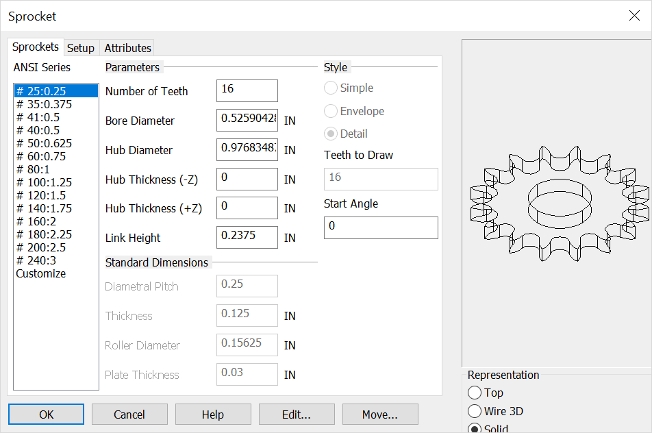
Dialog Options ANSI SERIESThe ANSI standard number (for example, #25) is followed by the pitch size for that standard (for example, 0.25) in inches. If you choose the "Customize" item from the ANSI Series list, the Standard Dimensions section options become available for the currently selected ANSI standard. PARAMETERSNumber of Teeth - Enter the number of teeth for the sprocket. Bore Diameter - Enter the bore diameter. (Enter "0" if you do not wish to draw a bore hole.) Hub Diameter - Enter the hub diameter size for the sprocket. Hub Thk [-z] - Enter the hub thickness for the -zv direction; "0" for no hub. Hub Thk [+z] - Enter the hub thickness for the +zv direction; "0" for no hub. Link Height - Enter the height for the links of the chain to be attached to the sprocket. This value cannot be greater than the diametral pitch of the sprocket, but must be greater than the roller diameter.
STANDARD DIMENSIONSThis section is available when you select Customize in the ANSI Series list. You can use the options in this section to customize a specific ANSI sprocket standard. Diametrical Pitch - The diametrical pitch for the sprocket is calculated as the number of teeth divided by the pitch diameter [Number of Teeth / Pitch Diameter]. Thickness - This is the thickness of the sprocket itself. 3D wire and solid representations of all mechanical elements are drawn in the -zv direction. Therefore, if you enter a negative number, the sprocket will be extruded in the +zv direction. Roller - Enter in the diameter of the roller portion of the chain. This determines the diameter of the sprocket teeth. The roller diameter must be greater than 0, and smaller than the diametrical pitch. Plate - This is the thickness (depth) of the plate portion of the chain link.
STYLEChoose the style for the sprocket. Simple - If you select Simple, only the pitch circle of the sprocket and a line representing the tooth depth will be drawn. Envelope - If you select Envelope, the outer diameter and inner diameter of the sprocket teeth will be indicated. Detail - If you select Detail, the entire sprocket will be drawn, including the tooth geometry.
REPSelect a representative (Top, Wire 3D or Solid) for the sprocket. |