KeyCreator / Verify / Deviation / Surface to Surface

Use this verify feature to measure the positional and normal angle deviations from one surface to another. The specified number of points will be distributed over the second surface in both the U and V directions. Each point will be evaluated for its minimum distance to the first surface selected. The surface normals at each point will be compared for parallelism.
When finished, the following information is displayed in the Data Verify dialog:
-
How many, if any, of the specified test positions on the two surfaces exceeded the positional deviation tolerance. The location of these points on the reference surface will be displayed using the current system attributes.
-
How many, if any, of the normal vectors at the specified test positions on the two surfaces exceeded the angular deviation tolerance. The normal vectors at the specified points on the reference surface will be displayed using the current system attributes.
-
The maximum positional and angular deviations, modeled as point and vector entities on both surfaces. By default, these entities are modeled using the color attribute red.
Using the Function:
-
Select Surface to Surfac from the Verify>Deviations submenu.
-
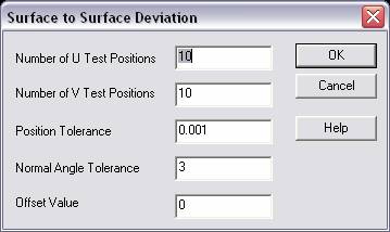
The Surface to Surface dialog box appears. Configure the available settings, and click OK.
-
Number of U Test Positions – Specify the number of test positions along the U direction of the surface to be evaluated.
-
Number of V Test Positions – Specify the number of test positions along the V direction of the surface to be evaluated.
-
Position Tolerance – Specify a value for the position tolerance. If the distance between the test positions on the two selected surfaces exceeds this tolerance value, the positions will be modeled as points on the reference surface.
-
Normal Angle Tolerance – Specify a value for the normal angle tolerance. If the distance between the test positions on the two selected surfaces exceeds this tolerance value, the positions will be modeled as vectors on the reference surface.
-
Offset Value – Specify a value for the offset. This value will compensate for an offset distance between the selected surfaces.
-
Select the reference surface (1st surface) to measure deviations from.
-
Select the surface to evaluate the deviations from the reference surface (1st surface).
-
The Data Verify dialog appears, displaying the verify information.
|