KeyCreator / Create / Solid Feature / Hole

Use this function to create a hole in a solid body. The hole will have a constant diameter. If a taper is required instead use the Pocket function. If a bend is required in the hole, instead use Boolean Subtract with a tool body the shape of the hole.
Using the Function:
The required steps might change depending upon what settings are chosen in the dialog box for the function.
-
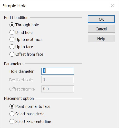
Select Hole from the Create>Solid Feature submenu. The Drill a Hole into a Solid dialog box appears, from which you are able to specify an end condition, drill parameters, and placement operations for the operation. These settings are explained below.
-
Once you have configured the dialog, select OK to accept any changes.
-
Indicate the face to be drilled.
-
Indicate the center point of the hole on the face. The hole is drilled where you indicate, and per the specifications made in the Drill… dialog box.
Dialog Options:
End Condition
The options in this section determine the end condition for the termination of the hole.
-
Through hole - Use this to create a hole all the way through the body.
-
Blind hole - This option creates a hole which travels only a specified depth in from the face. Enter the depth in the Depth of hole field.
-
Up to next face - If the body contains multiple faces along the axis of the hole, you can use this option to make the hole terminate at the first face encountered.
-
Up to face - If the body contains multiple faces along the axis of the hole, you can use this option to select which face should define the termination of the hole. You will be prompted to select the terminating face.
-
Offset from face - When this option is used, the terminating end of the hole will be defined by an offset depth in from a second selected face of the same body. Enter the offset as a positive value using the Offset distance field on the dialog box.
Parameters
The options under Parameters allow you to indicate a hole diameter, depth and offset distance. Note that one or more of these settings will be grayed out depending upon the End Condition that you select.
-
Hole diameter - Indicate a diameter value for the hole being created.
-
Depth of hole - Indicate a depth value for the drilled hole.
-
Offset distance - Allows you to indicate an offset distance for the drilled hole.
Placement Option
The Placement option box gives you three options for locating the center of the hole on the chosen face of the solid:
-
Point normal to face - Use this option when you want to use a point to define the center of the hole on the selected face. The point does not have to lie on the face. If it does not lie on the face, it will be projected onto the face along the normal vector of the face. The normal vector of the face will be used as the axis of the hole. You will use the Selection Menu (CURSOR, POINT, ENDENT, etc.) to select the point.
-
Select base circle - This option requires that a circle or arc entity be created prior to entering the Create hole routine. The diameter of the circle entity will be used as the diameter of the hole, the diameter entered on the dialog box will be ignored. The circle does not need to lie on the face, it will be projected onto the face using the normal vector of the circle entity. The normal vector of the circle will be used as the axis of the hole.
-
Select axis centerline - This option uses a line entity to define the center axis of the hole. The line itself does not need to intersect the face, it will be extended if necessary. The point where the axis intersects the face will be used as the center point of the circle.
|