KeyCreator / Create / Mesh / Tabulated Cylinder Mesh
Use this feature to create a mesh that visually simulates the surface defined by sweeping a generator curve along a linear path, the director, of a specified length.
Using the Function:
Two PositionsTwo Positions is selected by default. It defines the cylinder axis with a selected start point and end point. An axis vector is directed from the start point to the end point.
LineThis setting defines the cylinder axis with a selected line entity. The axis vector is directed from the end of the line closest to the selection point, to the opposite end of the line. Select a line to define the axis vector. End of EntityThis setting defines the cylinder axis with a selected line, arc, conic, polyline, or spline. The axis is defined as the outward-pointing tangent vector at the end of the entity, closest to the selection point. Select a line, arc, conic, polyline, or spline. Key InThis setting defines the cylinder axis with entered values for the axis vector coordinates, X, Y, and Z, either in world or view coordinates. Enter the X, Y, and Z vector components. Example Tabulated Cylinder: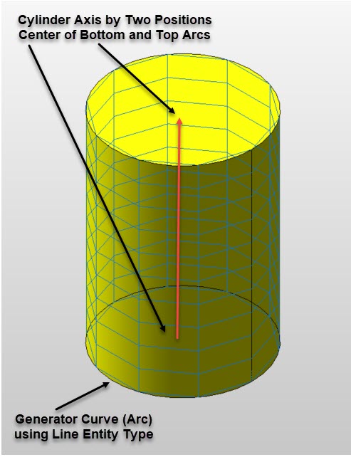 |