KeyCreator Prime / Solid / Sheetmetal / Edit Bend
Use this feature to edit a selected sheetmetal bend. Bends are selectable by their geometric shape. When this feature is selected, the Change Sheetmetal Bends dialog appears, identical to the Create Sheetmetal Bends dialog. The K-Factor of the bend is saved using the ACIS attributes for the model that were specified when it was created. If the bend belongs to a part that had been imported, the K-Factor value will read "Not Specified." In this instance, you are required to specify a K-Factor. Specify new parameters for the bend and OK the dialog. You are then asked to select the bend you wish to edit. Note: If other functions such as Modify>Warp>Bend have been used on the sheetmetal part this edit should be used after first running Tools >Maintenance>Simplify Bodies. Using the Function:
Dialog Options: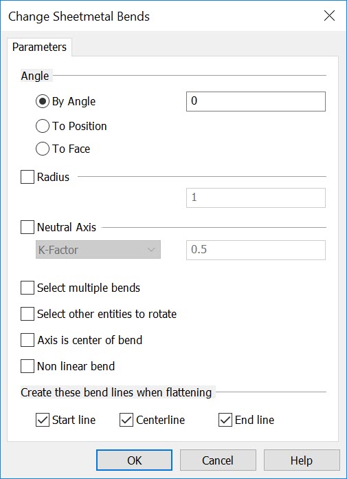 AngleThere are three methods by which the bend can be specified: By Angle, To Position, and To Face.
RadiusSpecify a value for the radius of the bend. NOTE: :Entering a value of 0 will create a 0.008 bend radius which is useful for any future sheet metal unbend actions.Sheet Metal 0 Radius Bend 
Neutral AxisWhen sheetmetal is bent, the inside surface of the bend is compressed. The outside surface is stretched. Within the thickness of the metal is the Neutral Axis – the line in the metal that is neither compressed nor stretched. For instance, if you were to work with a piece of sheetmetal with a 90 degree bend in which one leg measures X and the other Y, the total length of the piece when flattened wouldn’t be the sum of X+Y, but rather the result of the Bend Allowance, Bend Deduction, and K-Factor for the piece. Specify K-Factor, Bend Allowance, or Bend Deduction from the pull-down menu. You are then required to specify a value for whatever setting is selected. Bend Allowance refers to what needs to be added, Bend Deduction what needs to be subtracted. The K-Factor refers to the location of the neutral line, and is a ratio representing the location of the neutral sheet with respect to the part thickness. Select Multiple BendsWhen selected, and when two or more bends are allowed in the model, you can create multiple bends. The bends must be co-linear, but are not required to touch. Select Other Entities to RotateWhen selected, you will be prompted after creating the bend to select other entities to rotate about the axis. Using the Selection Menu, specify the entities you wish to rotate. The primary purpose for this feature is to re-locate axes. However, any entity type can be selected and rotated. Axis Is Center of BendWhen this setting is checked (ON), the part will unbend and re-bend along the center of the bend, instead of its start position. Non linear bendWhen selected, you can select a set of curves for the bend line (instead of one line). The curves should form a closed loop, or their linear extension should divide the part in two pieces. For example, if you offset the four arcs and lines of a flat box with rounded corners into the part, you should be able to select the four offset arcs and lines to bend. Create these bend lines when flatteningIf you select the Start line, Center line and/or End line check boxes when you unfold, the bend lines will be created in the model at the start location, center line location, and/or end location of the bend. |