KeyCreator Drafting / Detail / Tolerance Symbol / Surface Finish / Create a New Surface Finish DialogCreate a New Surface Finish Dialog OptionsThe Create a New Surface Finish dialog appears when you select Surface Finish from the Detail>Tolerance Symbol Ribbon area. This dialog contains two dialog tabs, Surface Texture and Attributes. The contents of the Surface Texture dialog page are listed below. The Attributes page is identical to the common Attributes dialog page used elsewhere in KeyCreator.
Dialog Options: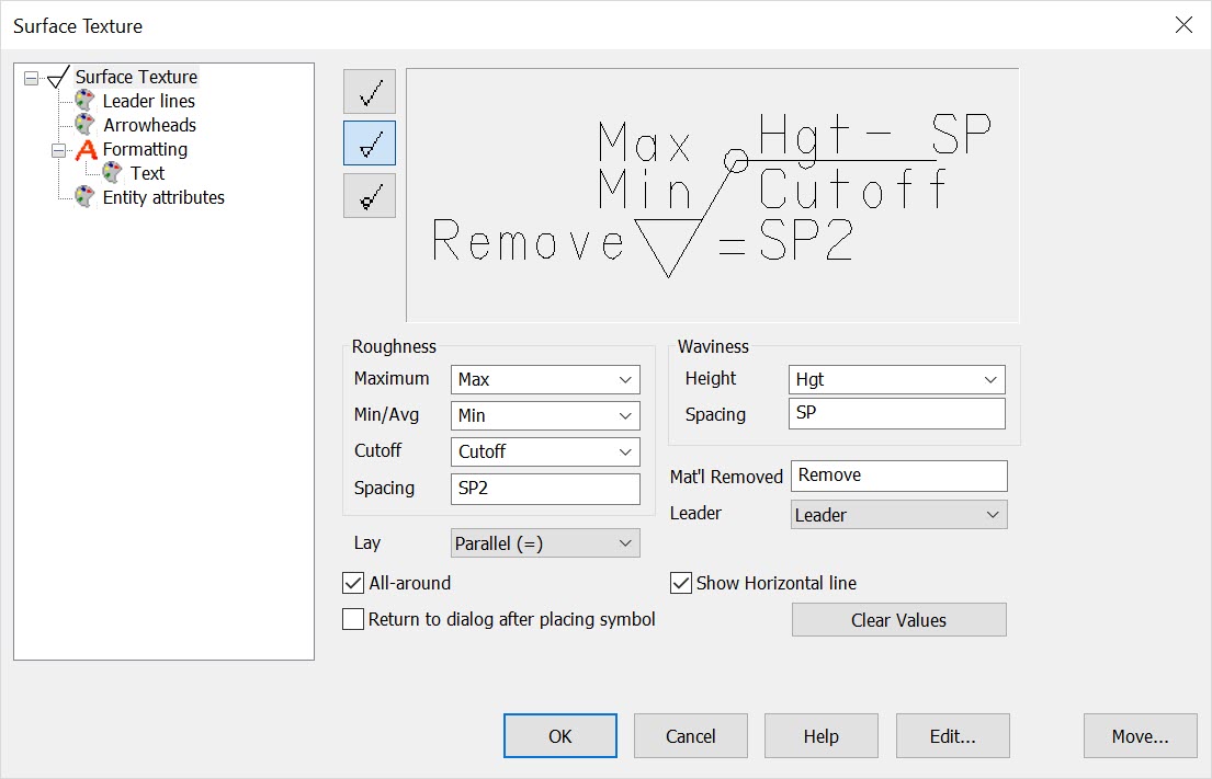 Symbol TypeSelect the type of surface texture symbol you want to create by clicking on the appropriate icon button. That symbol will appear in the preview window, and the name will appear next to Type. You can select from the following symbol types:
RoughnessSpecify a roughness type and value, by selecting either Maximum or Min/Avg. To remove a rating, delete the number in the text field and click ENTER, or choose a blank space from the list. Also under Roughness, you are able to specify a Cutoff rating as well as a Spacing value for maximum roughness width rating. WavinessSpecify a maximum waviness height rating, or select one from the pull-down list. If desired, you may enter a maximum waviness width rating in the Spacing text field. Note that if ISO Standards are selected in the Configuration dialog box, the Spacing text field will be replaced with a Production Method text field. Everything else under Waviness will be grayed-out LayChoose a lay symbol for the surface finish symbol. This symbol indicates the direction of the lay used for tooling. The following symbols are available: Blank for none, Parallel, Perpendicular, Crossed, Multi-dir, Circular, Radial, or Non-dir. Mat’LIf a Machining surface finish symbol was chosen, you can specify the amount of material to be removed by machining in the Mat’l text field. Note that otherwise, this setting is grayed-out. LeaderSelect a leader type for your symbol from the following types:
Leader - Draws a leader and arrowhead. Return to Dialog After Placing SymbolWhen checked, the Create a New Surface Texture dialog will re-appear once you have placed a surface texture symbol. All-Around
Adds the all around symbol at base of horizontal line of surface finish.
Show Horizontal Line
Choose to show or not show horizontal line when using the Material Not Removed surface finish style (bottom listed style in dialog).
CLEAR VALUES
When checked, all current values will be cleared, allowing you to enter new values for each dialog setting. Leader, Arrow and Entity AttributesThe settings dialog for these attributes are the same as those derived from the system settings for attributes, but will be unique to the Surface Finish being created. FormattingThe settings for formatting are derived from the detail formatting dialog but will be unique to the Surface Finish being created. |