KeyCreator Drafting / Assembly / Connection / Create / Options
Options
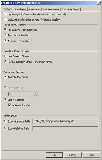
The following settings are available from the Options page of the Creating a New Part Reference dialog. Note that all settings in this page will be stored in the Windows registry, and retained from session to session.
Dialog Options:
Lightweight reference for visualization purposes only - When selected, the part reference is created with the lightweight flag enabled. This causes the part reference to display the lightweight data from the selected level set, if available. See Lightweight for further information.
Include detail entity in part reference display - When selected, causes the part reference to display details such as notes, labels, dimensioins and crosshatches from the referenced part.
Associativity Options
The following settings can be configured to determine whether the new part reference will be associative to the insertion plane, position, and rotation angle.
-
Associative Insertion Plane - When selected (checked), the part reference will retain the plane to which it was inserted, and will update according to any changes that are made to the insertion plane.
-
Associative Position - When selected (checked), the part reference will retain a link to the geometry used to locate it, and will update according to any change in this geometry.
-
Associative Rotation - When this setting is checked, the part reference being created will retain a link to the geometry used to locate it, and will update according to any change in this geometry.
Insertion Plane Options
Use the following options to select an insertion plane for the part reference. If Associative Insertion Plane is selected under Associativity Options, the part reference will be associative to the selected insertion plane.
-
Use Current CPlane - When selected (checked), the part reference will be inserted on the current CPlane. When this option is used, the part reference will carry a reference to the defining plane of the current CPlane. Thus, if the plane is later changed, the part reference will change. Note that the part reference will not change when you reconnect the CPlane to a new plane.
-
Define Insertion Plane Using Plane Menu- When this setting is checked, you will be required to define a plane using the plane menu on which the part reference being created will be inserted.
Placement Options
The following settings are used to determine how and at what rotation angle the new part reference will be inserted. See the Placing a Reference segment for information regarding how to insert a part reference into a design file.
-
Animate Placement - When checked, the part reference will be animated during selection of the base point. Note that if this setting is selected for large parts, it may cause significant delays, particularly, on smaller machines with low memory.
-
Key In Rotation - When this setting is selected (checked), you are able to key in a rotation angle, at which the part reference will be inserted into the selected file. Note that this option can only be enabled if the Associative Rotation setting under Associativity Options is unchecked.
-
Select Rotation - Allows you to select a rotation from a dialog containing recently used angles. Initially, this box will contain commonly used rotation angles.
-
Animate Rotation - When checked, the part reference will be animated as you choose a rotation angle. Note that you may experience delays when this setting is enabled for a large part reference; especially on smaller machines with low memory.
Path Options
The settings below can be set to dictate whether the file path will be remembered as either absolute or relative. The read-only edit fields will display the absolute and relative paths for you to select from. It is important to know the following when configuring this portion of the Creating a New Part Reference dialog:
-
If the referenced part is on a different drive than the referencing part, you can only select an Absolute path.
-
If the referenced part is in the same design file as the referencing part, both an absolute and relative path can be used.
-
If the referenced part is on a network drive, and the referencing part is located either on the same machine or a different network drive, UNC paths (\\server\path\filename.ckd) are recommended over paths that use mapped drive letters (for instance, d:\path\filename.ckd).
-
Store Absolute Path – The filename is listed here. If you select this setting, you can relocate the file containing the reference elsewhere and the link will remain valid, as long as the referenced part hasn’t moved.
-
Store Relative Path – The filename is listed here. If you select this setting, you can move the file containing the reference and the referencing file together. If they are both located on a network, they can be accessed from another computer with a different drive mapping.
|