Layout Mode OverviewKeyCreator Drafting / Drawing Layout / Overview / Layout Mode Overview
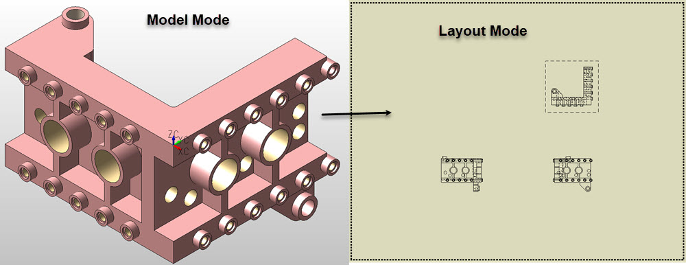
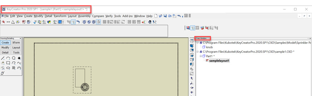
Working in Layout mode is similar to adapting your three-dimensional ideas to paper, making them two-dimensional. You can use Layout mode to detail and position multiple views, or drawing instances, of a part file in a two-dimensional format, (once a part has been constructed in Model mode). Through the available tools in Layout mode, you can place several two-dimensional views of a three-dimensional part file in one viewport without creating and placing separate pattern files of each view: Layout Mode naming convention "NewFile1[Part1] <NewLayout1>"
If the layout has been named, its name would appear in place of "New Layout 1." Its file name would appear in place of "NewFile1" and the model mode part name appears in the [] area. This would show in the upper left corner of KeyCreator and in the Tree Window: Layout Basics:
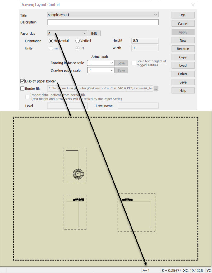
In a layout, a rectangular, dashed border representing the paper size of the border will be visible in the viewport and will surround the layout area, (toogle paper border display), as shown below: A drawing layout is a two-dimensional representation of different views of a part file. When creating a new layout, you are able to dictate layout-specific settings that are used to create it, such as: a layout name and description, paper size, drawing scale and instance views. These settings are configured through the Layout Control Dialog Box, (see Drawing Layout Control Dialog for more information). Notes on Layout Mode:
NOTE: Wire3D and Solid fastener representations CANNOT be created in layout mode.
To view information on a Layout topic, click on the appropriate link below: |