General Print ConfigurationKeyCreator Drafting / Tools / Settings / Customize Application / Print/Plot / General Print Configuration
The General pane contains the most common print/plot settings (e.g., print/plot region, paper orientation), and allows for the specifying of default values that will appear in the Setup dialog during the print sequence. It also controls the spacing in the pattern of dashed lines, and whether printing will be in portrait or landscape mode. Dialog Options: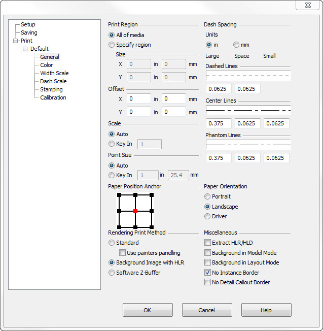
Print/Plot RegionThis setting allows selection of automatic or manual control of the print region size. The values you entere here will be the default values in the Setup dialog during the print sequence. All of MediaUse this setting to print or plot using the largest available paper region depending on how the printer or plotter was configured in Windows. When you use All of Media, the Size box is inactive. Specify RegionUse this setting to print or plot using a paper region that you specify. Specify Region allows you to set a smaller paper region to print or plot in. When you use Specify Region, you can specify a paper region using the Size boxes. SizeUse this setting to print or plot a region in inches or millimeters, by specifying X and Y values for the printing or plotting region in the Size box. Entering a value in the inches box automatically updates the value in the corresponding value in the millimeter box, and vice versa. OffsetThis setting sets the origin of the print or plot region in inches or millimeters to compensate for any default offset added by the printer or plotter. Enter X and Y offset values for the printer or plotter in the Offset box. You can have negative or positive offset values. When entering Offset values, you can enter X and Y values that move the printing and plotting region off the paper resulting in a clipped print or plot. Entering a value in the inches box automatically updates the value in the corresponding value in the millimeter box, and vice versa. ScaleUse Scale to scale your part to the paper size without distorting the part. Scale determines the ratio of part size to paper size. You can allow the program to automatically determine the scale, or you can choose your own scale. The values entered here will be the default values in the Setup dialog during the print sequence. AutoThis setting scales the part to automatically reach the extents of the paper margins. Key InThis setting allows you to enter a plotting scale value manually. AnchorUse Anchor to define the position from which you move the paper drag box. The position you select here entered here will be the default values in the Setup dialog during the print sequence. When you finish setting up the printer in the Printer Setup dialog box, you are then prompted to indicate a placement for the paper in the viewport. A rectangular highlighted paper border known as a drag box is then displayed. You can move the drag box to any position on your screen. The drag box allows you to set the paper around the part. Drag box boundaries match the print area size you set in the Printer Setup dialog box. Position the cursor in the Drag Point box and click on one of the cursor placement options: DashesUse these input fields to specify the sizes used for the line segments and spaces for the three dashed line types (dash, center, phantom) that are available. This value is then applied to dashed lines when they are printed. These values are expressed in either inches or millimeters. For each line type there is a display showing the line segments and spaces that make up the line. The three edit fields underneath control the size of the long dash, the space and the short dash respectively. Note that the Dashed Line type doesn't have a short dash so it only contains two input fields. These input fields contain the exact values of those segments and spaces. As you modify the values, the display field will update to show the new settings. Again, these settings do not affect the appearance of dashed lines in your drawing; only printed lines are affected. Note that all the gaps in center lines and the gaps as well as the two short dashes in phantom lines are defined to be the same size. This is standard in modern business practice. OrientationThis setting allows selection of either portrait or landscape as the default paper orientation for the current printer configuration. The orientation selected here will be the default values in the Setup dialog during the print sequence. Rendering Print MethodUse this option to control how to print in either the Flat or Smooth rendering methods. Three settings are available:
MiscellaneousThe following miscellaneous printing settings are available:
|