KeyCreator Drafting / Mechanical / Element / Gear

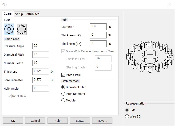
Gear teeth are created as spline entities approximating true involutes. Select Gear from the Mechanical >Element Ribbon area. The "Gears" dialog box will appear. Enter the information about the gear in this dialog box. Your selections will be displayed in the Preview window.
Dialog Options:
Spur
Select the type of gear to draw, Spur or Internal.
Dimensions
Enter the gear Dimensions. The choices are:
-
Pressure Angle - Enter the tooth pressure angle. The default is 14.5.
-
Diametral Pitch, Pitch Diameter, or Module - This choice is dependent on the setting selected in the Pitch Method section of this dialog box (see below).
-
Number Teeth - Enter the number of teeth for the gear.
-
Thickness - Enter the overall thickness for the gear.
-
Bore Diameter - Enter a diameter for the bore portion of the gear.
-
Helix Angle - Helical gears have teeth that are not parallel to the axis of rotation. To draw a helical gear, enter the helix angle in this text input field.
If a helix angle is specified, the Right Helix checkbox can be enabled to reverse the angle (in relation to the axis of rotation).
Hub
-
Diameter – Enter a diameter for the gear.
-
Thickness ( -Z) – The thickness of the center hub portion of the gear, extending in the current –Z place direction (i.e. the bottom of the hub).
-
Thickness ( +Z) – The thickness of the center hub portion of the gear, extending in the current + Z place direction (i.e. the top of the hub).
-
Draw with Reduced Number of Teeth – When selected, you can specify how many teeth will be included with the gear when it is drawn, as well as the starting angle.
Drawing Specifications
-
Teeth to Draw - Enter the number of teeth to draw.
-
Starting Angle - Enter the angle at which to begin drawing the teeth.
-
Draw Pitch Circle - Enable this checkbox if you would like to have the Pitch Circle included in your gear drawing.
-
Choose a Pitch Method option. This determines the method by which you will set the size of the gear in the "Gear" dialog box. The options are:
-
Diametral Pitch - The diametral pitch is calculated as the number of teeth divided by the pitch diameter [Number of Teeth / Pitch Diameter].
-
Pitch Diameter - Click on this radio button to set the size of the gear by selecting the diameter of the pitch circle.
-
Module - Click on this radio button to calculate the gear size as the pitch diameter divided by the number of teeth. (This is the inverse of the Diametral Pitch method.)
Rep
Choose a Representation for the gear. The choices are Top, Wire 3D.

Above > 2D and 3D Gears
NOTE: If you attempt to create invalid geometry, you will receive an error message and the previous (valid) dimensions will be displayed.
Setup
Attributes
|