Diagnose Solids and Sheet BodiesKeyCreator Drafting / Tools / Repair / Diagnose Solids and Sheet Bodies

This function performs a diagnosis of the selected solids and sheet bodies at a selected diagnostic level and optionally indicates those entities that check with problems. This function is intended for advanced users and programmers for use in diagnosing solids or sheet bodies that may exhibit unexpected results. The function is also useful if you have imported a file from another system (via STEP, IGES, Parasolid X_T etc.) and you wish to verify the integrity of the resulting solid and/or sheet bodies.
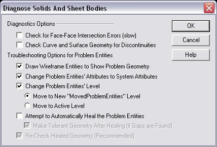
Dialog Options:
Diagnostics Options
-
Face-Face Intersection Errors - Check this option ON to check for faces that are not adjacent but still intersect. A typical case of these errors occurs in a solid that has multiple overlapping lumps. This type of error typically causes boolean operations to fail. This option will more than likely cause the verification to take longer to process.
-
Check Curve and Surface Geometry for Discontinuities - Check this option ON to detect curves or surfaces that are not continuous. Two curves or surfaces meet with C0 continuity if the positions of the entities at all points of their intersection are the same. G1 continuity requires the tangents at all points of their intersection to be in the same direction and have the same magnitude (C1 continuity varies from G1 in that only the directions of the tangent vectors are taken into account and not the magnitude). C2/G2 continuity requires the curvature at all points of their intersection to be the same. The ACIS modeling kernel that KeyCreator uses prefers that curves and surfaces generally be G2 continuous, but will allow G1 continuity at the knots of curves and surfaces.
Troubleshooting Options for Problem Entities
-
Draw Wireframe Entities Over Problem Geometry - If checked ON, wireframe entities are drawn over the problem areas of those solids/sheet bodies that verify with problems. The wireframe entities themselves are created on the level that the corresponding problem solid/sheet body will reside on based on the selection made in the ”r;Level to Place Problem Entities” category. These entities are drawn in color # 15 (white) and their line width is set to 3.
-
Change Problem Entities’ Attributes to System Attributes - If checked ON, the attributes of those solids/sheet bodies that verify with problems will be changed to use the current system attributes
-
Change Problem Entities’ Level - If checked ON, you are able to move the problem entities to a new level, or to the current active level.
-
Attempt to Automatically Heal the Problem Entities - If this checkbox is enabled, KeyCreator will attempt to heal any problem entities encountered during the verification. After attempting to heal the entities, it is recommended that you elect to Re-check the Healed Geometry. You can also elect to Make Tolerant Geometry.
|