KeyCreator / Verify / Body
The Body feature allows you to obtain data from a solid or Surface. Through the ”r;Verify Body Information” dialog that appears when this function is selected, you can obtain the size in bytes of the body, the topology count, tolerant entity count, and be able to run further diagnostics on the selected body. You are also able to view a .dbg file of the body by selecting the Details option, available from the dialog. You will also be informed if the body is manifold or non-manifold. A manifold body is one that is physically manufacturable. Examples of non-manifold bodies include two cones joined at the tips, or a face dangling off the edge of a block. HINT: To convert a non-manifold body into manifold components, use the Modify>Topology>Unstitch or Tools>Maintenance>Repair Non-Manifold function. Dialog Options:
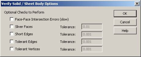
When Body is selected from the Tools>Verify submenu, the Verify Solid / Sheet Body Options dialog appears. You may elect to check one or more of the available settings, or none at all. However, even when a setting has not been enabled in the dialog, the selected body will be checked for problems that may cause downstream modeling. Face to Face Intersection ErrorsWhen selected, the body will be checked for faces that are not adjacent but still intersect. This typically occurs in a solid containing multiple overlaying lumps. This type of error has been known to cause some Boolean operations to fail. Note that when this setting is selected, the verification routine takes longer to process. Sliver FacesWhen selected, sliver faces that exist in the selected body will be detected. The Tolerance field associated with this setting allows you to determine which faces will be detected as slivers. Slivers are faces with at least 1 short edge shorter in length than the specified tolerance value, and at most 3 long edges longer in length than the specified tolerance. Short EdgesWhen selected, any short or tint edges in the selected body will be detected. The Tolerance field associated with this setting allows you to determine which edges are short. Short edges are edges shorter in length than the specified tolerance. Tolerant Edges and Tolerant VerticesWhen selected, the Verify Body function looks for tolerant edges and vertices. Those that have a tolerance value greater than the specified value are included n the count. The smallest tolerance you can enter is the coincident distance of 0.000001 (1e-006). We recommend maintaining the modeling coincident tolerance at 1e-006. These options allow you to ignore small problems at tolerances tighter than your application requires. For example, typical machining tolerance is 0.001. Using this value, the Verify Body function would find only edge and vertex gaps large enough to be a problem for machining. Using the Function:
|